96
KX-TH1211B/KX-TH1212B/KX-TGA930T
12.2.4. Adjust Battery Low Detector Voltage (Handset)
After handset's DSP (IC501) or EEPROM (IC541) replacement, Re-writing Battery Low voltage to EEPROM is required.
With following handset Adjustment Flow, adjust DC power supply and DC voltmeter by the procedure below.
1. Set DC power supply to 2.6 V.
2. Set up handset in TEST mode (Adjustment flow).
3. Press [1] key and [OFF] key to Adjust Batt Low mode. (“Bat Adj.” is displayed on LCD)
4. Change the voltage of the DC power supply to 2.34 V accurately. Check the voltage at P.C. board pads because some voltage
drops occur due to the usage of long or thin cables.
5. Press [TALK] key twice to write voltage value in EEPROM.
6. Press [TALK] key twice to write charge value 1 in EEPROM.
7. Change the voltage of the DC power supply to 3.1 V accurately.
8. Press [TALK] key twice to write charge value 2 in EEPROM.
9. Change the voltage of the DC power supply to 3.6 V accurately.
10. Press [TALK] key twice to write primary battery detect value in EEPROM.
11. Turn the power off. Then this value is available.
Note:
Refer to
Handset Reference Drawing
(P.98) for connection of DC power supply and voltmeter.
Cross Reference:
Adjustment Mode for Handset
(P.55)
12.2.5. Things to Do after Replacing IC (for BT Unit)
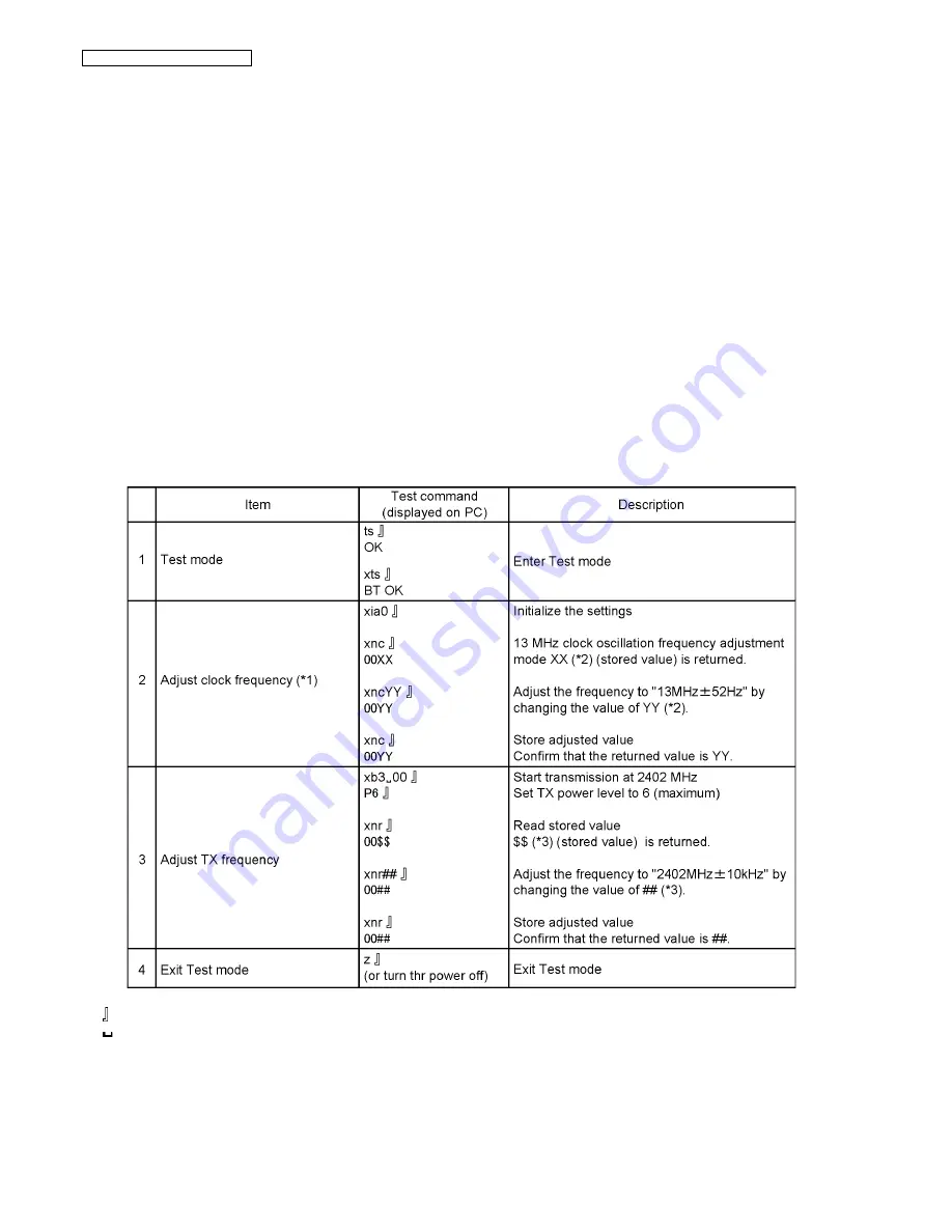
After replacing DSP or Program Flash on the BT board, the following adjustments are needed.
Turn the unit power on then start test mode with U-ART Jig on the main board.
Note:
: Enter key
: Space key
(*1) Connect Frequency Counter to the P.C.Board. Refer to
Base Unit Reference Drawing
(P.97).
(*2) XX and YY are hexadecimal data. Frequency decreases when the value of XX, YY increase, while it increases when XX,
YY decrease.
(*3) $$ and ## are hexadecimal data. $$, ## = 01
→
02 : 1 MHz up.
Summary of Contents for KX-TGA930T - Cordless Extension Handset
Page 2: ...2 KX TH1211B KX TH1212B KX TGA930T ...
Page 34: ...34 KX TH1211B KX TH1212B KX TGA930T 4 15 Signal Route ...
Page 35: ...35 KX TH1211B KX TH1212B KX TGA930T RF part signal route ...
Page 37: ...37 KX TH1211B KX TH1212B KX TGA930T 5 2 Display Indicators ...
Page 38: ...38 KX TH1211B KX TH1212B KX TGA930T 6 Installation Instructions 6 1 Connections ...
Page 42: ...42 KX TH1211B KX TH1212B KX TGA930T 7 1 2 Programming using the Direct Commands ...
Page 43: ...43 KX TH1211B KX TH1212B KX TGA930T ...
Page 44: ...44 KX TH1211B KX TH1212B KX TGA930T ...
Page 45: ...45 KX TH1211B KX TH1212B KX TGA930T 7 2 Error Messages ...
Page 46: ...46 KX TH1211B KX TH1212B KX TGA930T 7 3 Troubleshooting ...
Page 47: ...47 KX TH1211B KX TH1212B KX TGA930T ...
Page 48: ...48 KX TH1211B KX TH1212B KX TGA930T ...
Page 49: ...49 KX TH1211B KX TH1212B KX TGA930T ...
Page 50: ...50 KX TH1211B KX TH1212B KX TGA930T ...
Page 76: ...76 KX TH1211B KX TH1212B KX TGA930T ...
Page 89: ...89 KX TH1211B KX TH1212B KX TGA930T 11 1 2 Handset ...
Page 90: ...90 KX TH1211B KX TH1212B KX TGA930T 11 1 3 Charger Unit ...
Page 91: ...91 KX TH1211B KX TH1212B KX TGA930T 11 2 How to Replace the Handset LCD ...
Page 92: ...92 KX TH1211B KX TH1212B KX TGA930T ...
Page 100: ...100 KX TH1211B KX TH1212B KX TGA930T Memo ...
Page 105: ...105 KX TH1211B KX TH1212B KX TGA930T Memo ...
Page 109: ...109 KX TH1211B KX TH1212B KX TGA930T Memo ...
Page 114: ...114 KX TH1211B KX TH1212B KX TGA930T Memo ...
Page 118: ...118 KX TH1211B KX TH1212B KX TGA930T Memo ...
Page 130: ...130 KX TH1211B KX TH1212B KX TGA930T 15 5 DB56 DSP Package Description ...
Page 134: ...134 KX TH1211B KX TH1212B KX TGA930T 16 3 Cabinet and Electrical Parts Charger Unit ...
Page 135: ...135 KX TH1211B KX TH1212B KX TGA930T 16 4 Accessories and Packing Materials 16 4 1 KX TH1211B ...
Page 136: ...136 KX TH1211B KX TH1212B KX TGA930T 16 4 2 KX TH1212B ...
Page 137: ...137 KX TH1211B KX TH1212B KX TGA930T 16 4 3 KX TGA930T ...


