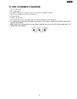
21 FOR SCHEMATIC DIAGRAM
1. SW101: Hook switch.
2. SW1: Ringer selector.
3. DC voltage measurements are taken with electronic voltmeter from negative voltage line.
4. (Add 40 mA to telephone line from the loop simulator.)
5. Off-hook condition
6. No Mack: Handset Mode
7. This schematic diagram may be modified at any time with the development of new technology.
8. The shades area on this schematic diagram incorporates special features important for protection from fire and
electrical shock hazards.
9. When servicing, it is essential that only manufacture´s specified parts be used for the critical components in the
shaded areas of the schematic.
43
KX-TSC11AGW
Summary of Contents for KX-TSC11AGW
Page 5: ...4 BATTERY 4 1 Installing the Batteries 5 KX TSC11AGW ...
Page 6: ...4 2 Battery Replacement 6 KX TSC11AGW ...
Page 7: ...5 LOCATION OF CONTROLS 7 KX TSC11AGW ...
Page 8: ...6 DISPLAY 8 KX TSC11AGW ...
Page 10: ...7 2 Dialing Mode 10 KX TSC11AGW ...
Page 13: ...8 OPERATIONS 8 1 Making Calls 8 2 Answering Calls 13 KX TSC11AGW ...
Page 14: ...8 3 For Call Waiting Service Users 8 4 FLASH Button 14 KX TSC11AGW ...
Page 15: ...8 5 Phone Book 8 5 1 Storing Names and Phone Numbers in Phone Book List 15 KX TSC11AGW ...
Page 16: ...Cross Reference Erasing P 21 Chain Dial P 20 16 KX TSC11AGW ...
Page 17: ...17 KX TSC11AGW ...
Page 19: ...8 5 3 Dialing from the Phone Book 19 KX TSC11AGW ...
Page 20: ...8 5 4 Chain Dial Cross Reference Dialing from the Phone Book P 19 20 KX TSC11AGW ...
Page 23: ...23 KX TSC11AGW ...
Page 26: ...11 4 No Ringing Sound When Ring Signal is Input 26 KX TSC11AGW ...
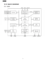
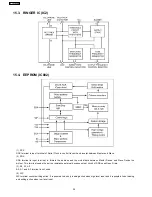
Page 32: ...15 IC BLOCK DIAGRAM 15 1 IC502 32 KX TSC11AGW ...
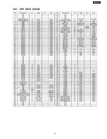
Page 33: ...15 2 CPU DATA IC502 33 KX TSC11AGW ...
Page 37: ...17 CABINET AND ELECTRICAL PARTS Note 1 Batteries are not included 37 KX TSC11AGW ...
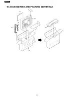
Page 38: ...18 ACCESSORIES AND PACKING MATERIALS 38 KX TSC11AGW ...
Page 39: ...19 TERMINAL GUIDE OF THE ICs TRANSISTORS AND DIODES 39 KX TSC11AGW ...
Page 46: ...22 1 Memo 46 KX TSC11AGW ...

