the cable. When you disconnect the cable, grip
the connector securely and pull it out.
General-purpose microphone
Connect the microphone to the Audio In L/R jack on
the back of the unit using the stereo pin plug cable
(
E
) after amplifying the signal to line level using a
device such as a microphone amplifier.
•
Connect the microphone correctly, as follows:
–
Left channel
®
L
–
Right channel
®
R
Note
•
When connecting both the Boundary
Microphone and a general-purpose
microphone, both microphones can be used
simultaneously.
•
When connecting a headset, refer to
"Headset Connection (Page 34)".
4.
Connect to the network.
•
Connect a hub/router to the LAN jack on the
back of the unit using a category 5 or greater
LAN cable (
F
).
Note
•
Set the hub/router to Auto Negotiation
mode.
•
Do not connect to a hub/router set to Half
Duplex.
•
For more details about routers and DCEs,
refer to the documentation for each device.
5.
Connect the power cord to the AC adaptor.
•
Use only the power cord included with the unit.
6.
Insert the AC adaptor’s DC cord (
G
) into the DC IN
terminal on the back of the unit.
•
Use only the AC adaptor included with the unit.
•
Wrap the DC cord around the hook to prevent it
from being disconnected.
7.
Plug in the power cord into the power outlet.
•
Choose an outlet that is convenient for
plugging/unplugging.
System Layout Examples
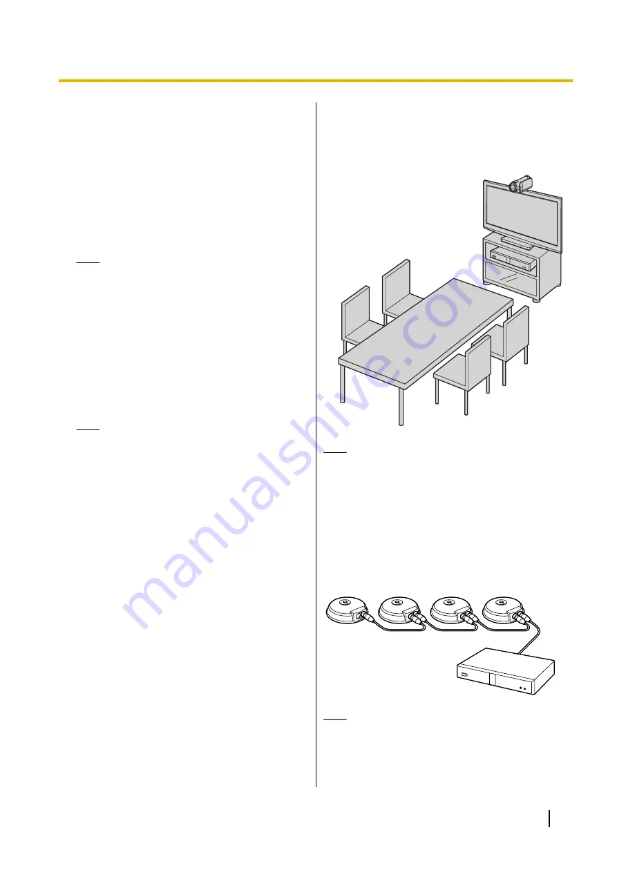
Display and Main Video Camera
Place the display and main video camera at the same
side of the room.
Note
•
If you use speakers, refer to "Amplifier/Active
Speaker Connection" (Page 35).
Digital Boundary Microphones
Up to 4 Digital Boundary Microphones can be
connected in cascade. There are no separate terminals
for input and output on the Boundary Microphones.
Also, an Analogue Boundary Microphone and
general-purpose microphones can be used
simultaneously.
Note
•
Make sure that the microphones are placed at
least 1 m (3.3 ft) away from the display and
speakers.
Document Version 2018-01
User Manual
31
Preparation


