6.
Plug in the power cord into the power outlet.
•
Choose an outlet that is convenient for
plugging/unplugging.
System Layout Examples
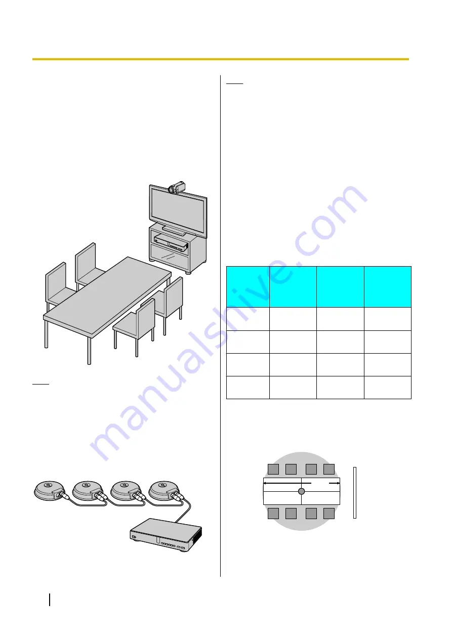
Display and Main Video Camera
Place the display and main video camera at the same
side of the room.
Note
•
If you use speakers, refer to "Amplifier/Active
Speaker Connection" (Page 23).
Boundary Microphones
Up to 4 Boundary Microphones can be connected in
cascade. There are no separate terminals for input and
output on the Boundary Microphones.
Also, Boundary Microphones and general-purpose
microphones can be used simultaneously.
Note
•
Make sure that the Boundary Microphones are
placed at least 1 m away from the display and
speakers.
•
Do not connect more than 4 Boundary
Microphones. Doing so will cause all Boundary
Microphones to stop working.
•
When 2 or more Boundary Microphones are
connected, if you want to change the output
sent to the other party to stereo, it is necessary
to configure the settings manually (Page 85).
•
If you are connected to an MCU or
non-Panasonic video conference system, the
output sent to the other party will be monaural.
The range of each microphone (the radius of the circle
with a microphone at the centre) varies according to the
level of surrounding and the number of microphones
being used. Place microphones accordingly, referring
to the following table.
Noise
level/
Micro–
phone
A quiet
room
(40
dBsplA)
A regular
room
(45
dBsplA)
A noisy
room
(50
dBsplA)
1
approx.
3 m
approx.
2.2 m
approx.
1.2 m
2
approx.
2.8 m
approx.
1.5 m
approx.
1 m
3
approx.
2.3 m
approx.
1.3 m
—
4
approx.
2 m
approx.
1.1 m
—
Layout examples (a regular room)
(the grey circle indicates the microphone’s range):
Display
Microphone
4 m
22
User Manual
Preparation


