


8
9
Electrical Work
■
Electrical requirements
■
Electrical connections
- This appliance must be supplied with the proper voltage and frequency, and
connected to an individual, properly grounded branch circuit, protected by a
circuit breaker or fuse. (The rating plate is on the bottom of the appliance.)
- Means for disconnection must be incorporated in the fixed wiring in
accordance with the wiring rules.
- You must use a three-wire, single-phase A.C. 240 V, 40 A, 60 Hz electrical
system. If you connect to aluminum wiring, properly use connectors
approved for use with aluminum wiring.
- Check with the local utilities for electrical codes applied in the area.
Failure to wire the appliance according to governing codes may result in
a hazardous condition. If there are no local codes, the appliance must be
wired and fused to meet the requirements of CSA and CEC.
- After installation, show the customer where the breaker for the appliance is located.
1. Turn off power.
Turn off power at the circuit breaker or remove fuses to the appliance
branch circuit.
2. Connect the power cord.
Connect the power cord in accordance with all governing codes and
ordinances.
WARNING
Electrical work must be
performed by a legally
qualified electrician.
E L2 L1
Connect
to the
ground
terminal.
Connect
to the line
terminal.
Yellow / Green
Black
Red
CAUTION
For your safety, remove
the plastic cover from
the power cord before
performing electrical work.
- In accordance with the electrical wiring rules, incorporate the earth leakage
circuit breaker in the home electrical wire.
- Follow the specification of the earth leakage circuit breaker as follows.
Rated current: 40 A, rated sensitivity current: 30 mA
■
Installation of the earth leakage circuit breaker
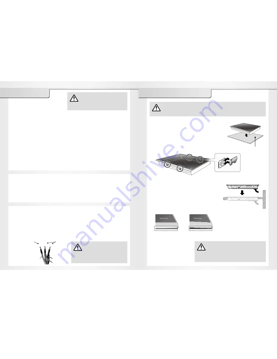
2. Embed the main unit in the countertop cutout
while keeping it is as level as possible.
- Do not drop the unit on the countertop.
- Press down on top of the main unit to make sure
that the frame is solidly rest on the countertop.
- Make sure that the spaces between the
countertop and the under surface of the top
frame are even in the front, back, left and right.
Installing the Appliance
Correct
Incorrect
WARNING
Do not disassemble the top plate.
Connected wire may become loose
and cause a malfunction.
CAUTION
If the cabinet does not have an
opening in the front, the wiring needs
to be connected before the main unit
is embedded into the countertop.
1. Fasten the clamps to the main unit
(4 places on the front and back).
- Put the Cardboard A underneath the main unit to act
as a buffer in order to prevent the countertop from
getting damaged.
- Match the clamp grips with the holes on the sides of
the main unit, then slide the clamp from the right to
the left to fasten them to the main unit.
Cardboard A
3. Connect the power cord
See page 8.


