background image

10

Post-installation Checklist

Upon completing installation, check and mark off the following items.

I hereby certify that installation has been completed.


Signature of installer

Checklist

Checked

Appearance

 - Does the appliance not look like it is tilted to the front, 

back, left or right?

 - Is the frame not lifted up?

 - Is the top plate clean?

Electrical 

work

 - Is the power supply a single phase, 240 V?
 - Has the ground been installed?

 - Has the earth leakage circuit breaker been installed?

Electrical 

testing

1. Touch 

 to turn on the main power.

 - Does the main power light light up?

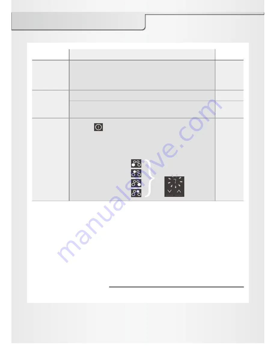
2. Touch the following keys to check function of each 

IH heater:

 - Left front heater
 - Left rear heater
 - Right front heater
 - Right rear heater

 - Make sure to turn off each IH heater and the main power switch after performing 

electrical testing.

 - Hand the Operating Instructions, Installation Instructions, and Warranty Certificate to 

the customer.

Does "7" (heat 

level display) 

flash?

Panasonic Canada Inc.

5770 Ambler Drive, Mississauga, Ontario, L4W 2T3

www.panasonic.ca

© Panasonic Corporation 2011

Printed in Japan

Summary of Contents for KY-B84AX

Page 1: ...llation Location 4 Accessories 4 Dimensions 5 Related Dimensional Drawings for Custom Kitchens 6 Electrical Work 8 Installing the Appliance 9 Post installation Checklist 10 Installation Instructions Induction Heating Cooktop Model No KY B84AX KY B84AG ENGLISH ...

Page 2: ...pliance in accordance with the Installation Instructions Otherwise the performance of the appliance may be affected Make sure to perform a test run and explain to the customer how to properly use the appliance Proper installation is the responsibility of the installer Any malfunction or accident resulting from the failure to follow Installation Instructions is not covered under guarantee Hand thes...

Page 3: ...allation Location Observe the laws concerning the installation of the appliance 4 pieces For more details on cutout see page 6 Clamp Intake vent Exhaust vent Cooking zone Min 51 mm clearance from cutout to rear wall Max 330 mm depth of cabinets Min 51 mm clearance from cutout to side wall Cutout Min 762 mm clearance from the top of the cooktop to the bottom of the cabinets Dimensions 83 74 57 723 ...

Page 4: ...tertop front Min 59 Building side wall Building rear wall Min 30 for flat part Bulge of front countertop Rear side Front side Intake Shelf Exhaust Min 300 for vertical clearance Flow of intake and exhaust Min 170 Min 51 Min 600 Min 51 Min 51 Allow for a minimum of 95 mm extra space between the countertop and the top surface of the oven for air circulation Rear side Front side Exhaust Flow of intak...

Page 5: ... line terminal Yellow Green Black Red CAUTION For your safety remove the plastic cover from the power cord before performing electrical work In accordance with the electrical wiring rules incorporate the earth leakage circuit breaker in the home electrical wire Follow the specification of the earth leakage circuit breaker as follows Rated current 40 A rated sensitivity current 30 mA Installation o...

Page 6: ...e earth leakage circuit breaker been installed Electrical testing 1 Touch to turn on the main power Does the main power light light up 2 Touch the following keys to check function of each IH heater Left front heater Left rear heater Right front heater Right rear heater Make sure to turn off each IH heater and the main power switch after performing electrical testing Hand the Operating Instructions...

Reviews: