Installation of this unit
Preparatory work for installation
14
Unpack the container box according to the following
procedure.
≥
A higher working space is recommended, such as a desk,
for ease of attaching a mounting bracket or removing a
reinforcing plate.
1
Unpack the container box for shipping, detach
the side plates, and remove buffer materials.
2
Lift up the unit to move it to the work area.
≥
Stick your hand into the gap between the unit and the box, and
hold the bottom of the unit to lift it up. Since the interface side
of the Base Module and Extension Module (with the Writer
Unit) are heavier, keep the unit balanced with several people.
≥
In the working space, prepare each module following the
"Installation" (
24) and then move the unit holding the bottom.
≥
Be sure to follow the instructions on page 16 when doing the work.
≥
Accessories are stored in a box to the interface side of
the unit and beneath the unit.
Prepare the racks to install the modules. Refer to "Racks that
can accommodate this unit" (
5) for rack conditions.
≥
Install the panel mount frames so that the ones on the front
and rear sides are 660 mm (26.0
q
) to 790 mm (31.1
q
) apart.
≥
Install the drawer-side’s panel mount frames so that the
distance between an imaginary line formed by these frames
and an imaginary line extending horizontally from the
projection on the inner surface of the rack’s drawer-side
door will be 55 mm (2.2
q
) to 115 mm (4.5
q
). (The frames can
be adjusted in 3 steps at 20 mm (0.8
q
) intervals)
≥
Leave a space of at least 1400 mm (56.0
q
) at the drawer side so
that all magazine drawers can be pulled out for maintenance.
≥
Determine the position in the lower part where the Bottom
Module is to be installed. The lower part of the Base Module
or Extension Module is placed in the 4U upper position from
the lower part of the Bottom Module.
≥
Confirm that there is no deformation of the panel mount frame in the
rack. We recommend replacing the rack if there is any deformation.
≥
Make a record of any deformations, etc., in the rack. There
may be problems with the tasks described in "Connecting
the gear rack" (
27) if there are deformations.
1
Check the front and rear spaces in the rack.
≥
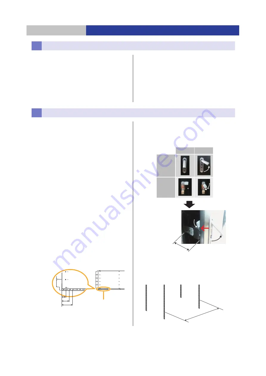
The mounting brackets of this unit can be adjusted in
three levels. Refer to the dimensions below to adjust
the mounting brackets. The mounting brackets are
fixed to the 14 mm (0.6
q
) position (The most drawer
side of the 3 steps) of all modules at the time of
shipment. Align the mounting brackets of all the
modules to be installed in the same rack with the
locating holes of the same level.
2
Check the space available for when the door is
open on the drawer side of the rack.
≥
Confirm that the lock mechanism on the inside of the door on
the drawer side of the rack does not interfere with the
magazine drawer when it is open (maximum 90 mm (3.5
q
)).
3
Check the front and rear spaces of the panel
mount frame.
≥
The panel mount frame can be installed in the space
between 660 mm (26.0
q
) and 790 mm (31.1
q
).
≥
Adjust the position of the panel mount frame of the
rack as needed.
Unpacking a container box
Preparation of rack
14 mm (0.6
)
34 mm (1.3
)
54 mm (2.1
)
Side of the Base Module
Locating holes
Close
Open
Door knob
(Front)
Door Lock
(Inside)
Max. 90 mm (3.5
q
)
For example: There is
interference with the lock
mechanism of the door
when the magazine drawer
is open, and the door
cannot be opened.
660 mm (26.0
) to
790 mm (31.1
)
Panel mount
frame


