Installation of this unit
Installation
27
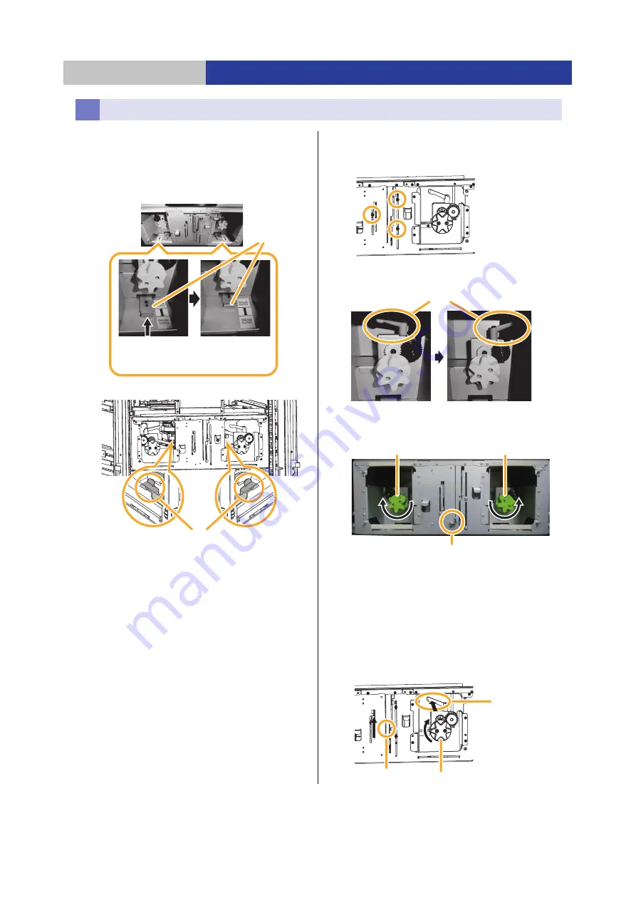
1
Turn off the drive transmission of the changer
unit.
≥
Insert your hands into the opening to left and right.
Then push the clutch release arm.
≥
Make sure that the clutch release arm is stationary and
does not return.
≥
Do not touch the levers in the changer unit.
2
Remove the gear rack fixture.
≥
Loosen the three screws of the gear rack on the drawer
side (do not remove them to secure the gear rack later).
≥
Rotate two clamping levers in the left and right
counterclockwise to loosen.
≥
Turn the left handle clockwise until it stops.
≥
Turn the right handle counterclockwise until it stops.
≥
Check that the protruding part is at the lowest part.
3
Connect the right gear rack on the interface side.
≥
Insert your hand into the opening at the bottom panel
side and turn the right handle clockwise to raise the
gear rack.
≥
The right gear rack on the interface side and the gear rack
on the drawer side are linked. While pushing up the
protruding part on the bottom panel side, turn the handle.
≥
Allow the gear rack to rise until there is no gap between the
Base Module or Extension Module and the gear rack, and
then turn the right clamping lever clockwise to secure it.
Connecting the gear rack
Clutch
release arm
Engage Clutch
(Default/Shipping)
Release Clutch
(Service)
Levers in the changer unit
Clamping lever
Protruding part
Right handle
Left handle
Right handle
Protruding part
Clamping lever


