Installation of this unit
Installation
35
4
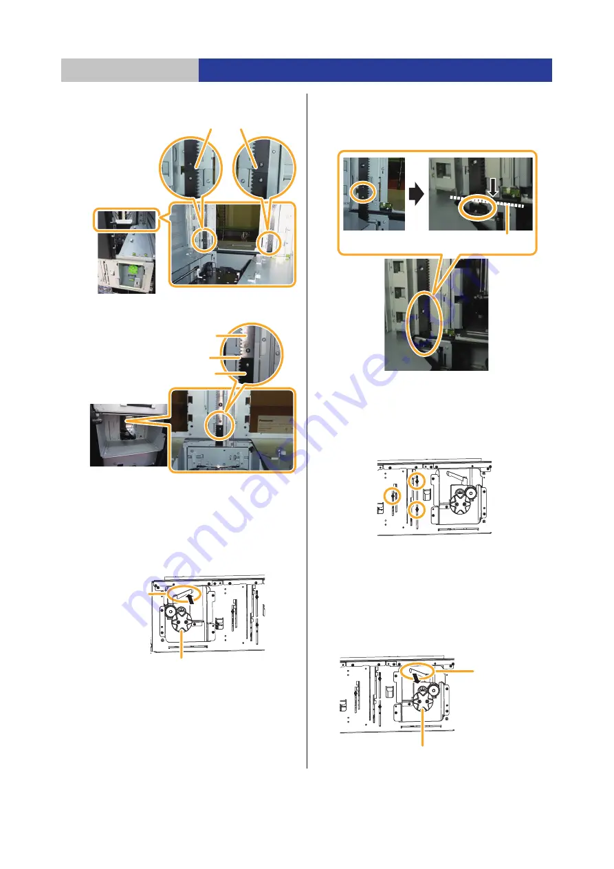
Check the connection of the gear racks.
≥
Interface side
≥
Drawer side
5
Disconnect the left gear rack on the interface
side.
≥
Insert your hand into the opening at the
bottom panel
side of the Bottom Module and turn the left clamping
lever counterclockwise to remove the gear rack fixture.
≥
When the gear rack fixture is released, the gear rack is
lowered automatically. Be careful not to pinch your
fingers because the handle will rotate automatically.
≥
Check that the gear rack of the Bottom Module is lower
than the module's border line. If it is not lower than the
border line, turn the left handle clockwise to lower the
gear rack below the border line.
6
Disconnect the gear rack on the drawer side.
≥
Loosen the three securing screws and remove the
gear rack fixture.
≥
The gear rack on the drawer side is linked to the right
gear rack on the interface side and it is not
automatically lowered.
7
Disconnect the right gear rack on the interface side.
≥
Insert your hand into the opening at the bottom panel
side of the Bottom Module and turn the right clamping
lever counterclockwise to remove the gear rack fixture.
≥
When the gear rack fixture is released, the gear rack is
lowered automatically. Be careful not pinch your
fingers; the handle will be rotate automatically.
≥
Please note that the gear rack on the drawer side is
linked and it is automatically lowered.
Check the state of the connections.
Check the state of the connections.
Gear rack (Extension
Module)
Gear rack (Bottom
Module)
Left handle
Clamping lever
Border line of the module
Left side of the interface side
Clamping lever
Right handle


