Installation of this unit
Preparatory work for installation
21
7
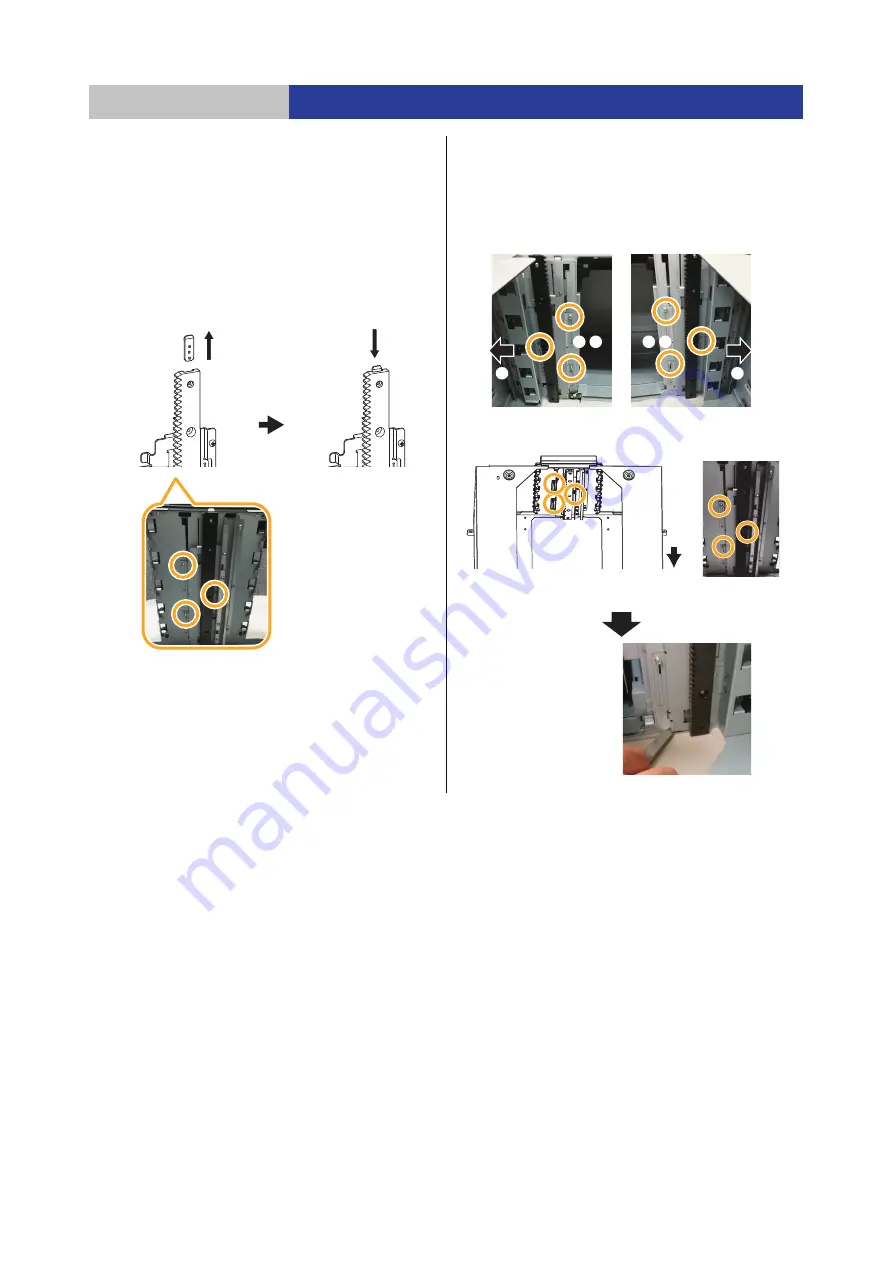
Relocate the connection plate of the topmost
module (3) and place it on the Base Module.
≥
The work is not required if the Base Module is placed
on the top.
≥
The connection plate is secured at the top of the gear rack by
a screw. Remove the screw and remove the connection
plate, and then secure the connection plate to the top of the
Base Module gear rack with the same screw.
≥
Use bit #1 driver with the M2.6 screw.
Torque: 0.5 Nm
n
10 % (4.5 in-lbs
n
10 %)
8
Tighten the screws while pressing the gear
rack for the module to be placed at the top
against the bottom surface. (3 locations
k
3)
≥
This step is not required if the Base Module is to be
placed at the top.
Module to be
placed at the top
Base Module
Gear rack
It is easier to remove the
connection plate by
removing the screws and
lifting the gear rack.
Left gear rack on
the interface side
1
Loosen the screws
2
Push the rack out
3
Tighten the screws
After securing, confirm that
a 2.7 mm (0.11
q
) gap gauge
cannot be inserted.
Right gear rack on
the interface side
Gear rack on the drawer side
Interface side


