Installation of this unit
Power supply installation
46
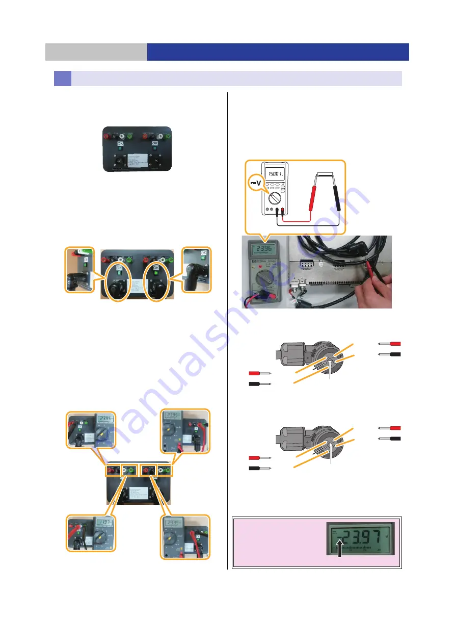
When using the DA power checker
Use the DA power checker to check that the DC cable
connection and the voltage are correct.
Checking connections
1
Connect the DC cable to the DA power checker.
2
Check the LED.
Illuminated: OK (connections correct)
However, this does not indicate that voltage is correct.
Voltage is checked in step 3.
Not illuminated: Connections incorrect. Recheck the
power supply connections.
Checking voltage
3
Use the multimeter to check the voltage.
≥
Voltage specifications
24 V: 22.8 V to 25.2 V (3 locations)
2 locations on the Bottom Module (
12
in the below image)
1 location on the Base Module/Extension Modules
(with the Writer Unit) (
3
in the below image)
12 V: 11.4 V to 12.6 V (1 location)
1 location on the Base Module/Extension Modules
(with the Writer Unit) (
4
in the below image)
≥
If the voltage is outside of the specification ranges,
recheck the connections and the adjustment trimmer.
When not using the DA power checker
Measure the voltage using the following procedure when you
do not have a DA power checker.
1
Use the multimeter to check the voltage.
≥
Before connecting to the DATA ARCHIVER module, use
a multimeter to check the voltage on the four parts of the
connector (
A
to
D
) as shown in the below image.
≥
Measurement locations
≥
Voltage specifications
ABC
: 22.8 V to 25.2 V
D
: 11.4 V to 12.6 V
≥
If the voltage is outside of the specification ranges,
check the connections of all DC cables.
Checking voltage
Note:
If minus (
j
) is
displayed, the connections
are back to front.
(
) RED
(
) BLACK
NC
DC+24 V
GND
DC+24 V
GND
DC+12 V
GND
DC+24 V
GND
NC
White triangle pointing down
White triangle pointing to the right
DC cable for +24 V
(Bottom Module)
DC cable for +24 V/+12 V
(Base Module/Extension Module (with the Writer Unit))
Error


