2
TABLE OF CONTENTS
PAGE
PAGE
1 Safety Precautions
-----------------------------------------------
3
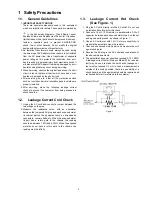
1.1. General Guidelines ----------------------------------------3
1.2. Leakage Current Cold Check ---------------------------3
1.3. Leakage Current Hot Check (See Figure. 1)--------3
2 Warning
--------------------------------------------------------------
4
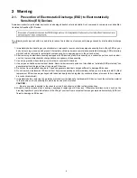
2.1. Prevention of Electrostatic Discharge (ESD)
to Electrostatically Sensitive (ES) Devices ----------4
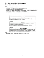
2.2. How to Replace the Lithium Ion Battery--------------5
3 Service Navigation
------------------------------------------------
6
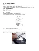
3.1. Introduction --------------------------------------------------6
3.2. Important Notice -------------------------------------------6
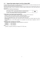
3.3. General Description About Lead Free Solder
(PbF) ----------------------------------------------------------8
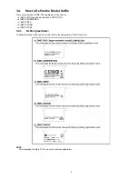
3.4. How to Define the Model Suffix-------------------------9
4 Specifications
----------------------------------------------------
10
5 Location of Controls and Components
------------------
12
6 Service Fixture & Tools
---------------------------------------
13
6.1. Service Fixture and Tools ------------------------------ 13
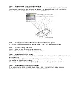
6.2. When Replacing the Main P.C.B. Unit -------------- 13
7 Disassembly and Assembly Instructions
---------------
14
7.1. Disassembly Flow Chart-------------------------------- 14
7.2. P.C.B. Location ------------------------------------------- 14
7.3. Disassembly Procedure -------------------------------- 15
7.4. Removal of the MOS Unit------------------------------ 20
7.5. How to Use Servicing Tool for Assembling -------- 20
8 Measurements and Adjustments
--------------------------
23
8.1. Matrix Chart for Replaced Part and Necessary
Adjustment------------------------------------------------- 23
9 Maintenance
------------------------------------------------------
24
9.1. Cleaning Lens and LCD Panel ----------------------- 24
Summary of Contents for Limux DMC-CM1GC
Page 11: ...11 ...
Page 16: ...16 7 3 1 Removal of the LCD Module Unit and Front Cover Unit Fig D1 Fig D2 ...
Page 17: ...17 Fig D3 Fig D4 ...
Page 18: ...18 Fig D5 7 3 2 Removal of the Lens Unit and Main P C B Unit Fig D6 ...
Page 21: ...21 7 5 2 How to install the LCD Module Unit ...
Page 22: ...22 ...


