– 108 –
Chapter 6 Input/Output Signal Settings — Setting input signals
Setting input signals
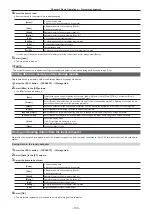
The rear of the Gateway Unit is equipped with SDI connectors for input and output.
f
Each Gateway Unit can accept input 12G SDI signals from 10 systems.
f
To configure the input signal settings, select the <IN OUT> button on the top menu
→
[SDI IN 1] to [SDI IN 20].
f
The frame synchronizer setting and freeze setting can be set for all the terminals on each of the input boards.
Setting the frame synchronizer
The frame synchronizer can be set enabled/disabled for each input.
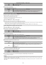
1
Select the <IN OUT> button
→
[SDI IN 1] to [SDI IN 20]
→
[Frame Buffer] tab.
2
Select an item in [FS] in the [SDI IN 1] to [SDI IN 20] columns.
[On]
Enables the frame synchronizer function.
[Off]
Disables the frame synchronizer function.
f
When the output signal phase is set to [0H], [FS] cannot be set to [Off].
For details, refer to “Setting the output phase”.
@
@
NOTE
t
Line synchronizer function is active while the frame synchronizer function is set to [Off].
t
The line synchronizer function automatically adjusts the input video signal phase to the horizontal sync signal phase.
For details, refer to “Setting the output phase”.
Freezing input signals
The input signals can be frozen and used. While signals are frozen, the tally signals of the corresponding input will not be output. When the system
format is progressive, the menu is not displayed and settings are not possible.
Setting the freeze mode
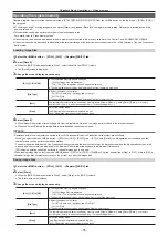
1
Select the <IN OUT> button
→
[SDI IN 1] to [SDI IN 20]
→
[Frame Buffer] tab.
2
Select an item in [Freeze] in the [SDI IN 1] to [SDI IN 20] columns.
f
An item can also be selected while an image is frozen.
[ON]
Freezes the images frame by frame.
[OFF]
There is no freezing.
Setting the source name
The source names displayed on the Control Panel and the MultiView display can be set from the <NAME> button on the top menu
→
[SDI IN]/[IP IN]/
[INTERNAL]/[ME]/[DSK]/[AUX]/[MV]
→
[Panel Name]/[MV Name] tab.
For details, refer to “Setting the source name”.
Displaying video input signal information
Displaying the SDI input signal information
Display the information concerning the SDI input signal images.
f
The information cannot be changed.
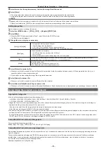
1
Select the <IN OUT> button
→
[SDI IN 1] to [SDI IN 20]
→
[Status] tab.
2
Check the [SDI IN 1] to [SDI IN 20] columns.
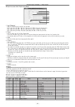
[Format]
Displays the input format.
When there is no input signal, [No signal] is displayed.
For formats that are not supported, [Undefined] is displayed. If horizontal pixels are the same, false detection may occur.
Summary of Contents for Live Production Suite Series
Page 5: ...Please read this chapter and check the accessories before use Chapter 1 Overview ...
Page 11: ...This chapter describes installation and connection Chapter 2 Installation and Connection ...
Page 50: ...This chapter describes menu operations Chapter 5 Basic Operations ...
Page 113: ...This chapter describes the configuration of operations Chapter 7 Configuring Operations ...
Page 122: ...This chapter describes how to operate system menus Chapter 8 System Menu ...
Page 136: ...This chapter describes plug in functions Chapter 9 External Interfaces ...
Page 140: ... 140 Chapter 10 Specifications Dimensions Dimensions of the XPT Unit AV LSX10 Unit mm inch ...
Page 141: ... 141 Chapter 10 Specifications Dimensions Dimensions of the ME Unit AV LSM10 Unit mm inch ...
Page 153: ...This chapter describes the setting menu table and terms Chapter 11 Appendix ...
Page 176: ...Web Site https www panasonic com Panasonic Corporation 2020 ...

