– 120 –
Chapter 7 Configuring Operations — Setting the operation mode
r
AV-HS60C2
CHR
LIN
LUM
FULL
4
SDI
IN3
3
SDI
IN2
2
SDI
IN1
1
Black
24
23
22
21
20
19
18
17
16
15
14
13
12
11
10
SDI
IN9
9
SDI
IN8
SDI
IN11
SDI
IN12
Still
1V
Still
2V
Still
3V
Still
4V
Clip
1V
Clip
2V
Clip
3V
Clip
4V
CBGD
1
ME1
PGM
ME2
PGM
SDI
IN10
8
SDI
IN7
7
SDI
IN6
6
SDI
IN5
5
SDI
IN4
RECALL
STORE
DEL
RECALL
CBGD
STORE
DEL
MIX
02s01f
MIX
01s00f
MIX
01s00f
WIPE
01s00f
CHR
LIN
FULL
FULL
WIPE
01s00f
MIX
01s00f
MIX
01s00f
MIX
CG5V
CG6V
CAM1
CAM2
CG5V
CG6V
CAM1
CAM2
CG1V
CG2V
CG3V
CG4V
01s00f
MIX
ME2
01s00f
MIX
ME1
01s00f
BUS
SHFT
BUS
SHFT
1-7
4-1
1-8
1-9
SHOT000
1-1
SHOT001
1-2
SHOT002
1-3
SHOT003
1-4
1-5
1-6
PLAY
SEL
AUK
DSK
ME2
XPT
ME1
4
SDI
IN3
3
SDI
IN2
2
SDI
IN1
1
Black
24
23
22
21
20
19
18
17
16
15
14
13
12
11
10
SDI
IN9
9
SDI
IN8
SDI
IN11
SDI
IN12
Still
1V
Still
2V
Still
3V
Still
4V
Clip
1V
Clip
2V
Clip
3V
Clip
4V
CBGD
1
ME1
PGM
ME2
PGM
SDI
IN10
8
SDI
IN7
7
SDI
IN6
6
SDI
IN5
5
SDI
IN4
4-3
4-2
4-4
4-6
4-5
4-7
4-9
4-8
OP
STILL1
1st Line
2nd Line
r
AV-HS60C4
CHR
LIN
LUM
FULL
4
SDI
IN3
3
SDI
IN2
2
SDI
IN1
1
Black
16
15
14
13
12
11
10
SDI
IN9
9
SDI
IN8
SDI
IN11
SDI
IN12
Still
1V
Still
2V
Still
3V
SDI
IN10
8
SDI
IN7
7
SDI
IN6
6
SDI
IN5
5
SDI
IN4
RECALL
STORE
DEL
RECALL
CBGD
STORE
DEL
MIX
02s01f
MIX
01s00f
MIX
01s00f
WIPE
01s00f
CHR
LIN
FULL
FULL
WIPE
01s00f
MIX
01s00f
MIX
01s00f
MIX
CG5V
CG6V
CAM1
CAM2
CG5V
CG6V
CAM1
CAM2
CG1V
CG2V
CG3V
CG4V
01s00f
MIX
ME2
01s00f
MIX
ME1
01s00f
BUS
SHFT
BUS
SHFT
1-7
4-1
1-8
1-9
SHOT000
1-1
SHOT001
1-2
SHOT002
1-3
SHOT003
1-4
1-5
1-6
PLAY
SEL
AUK
DSK
ME2
XPT
ME1
4
SDI
IN3
3
SDI
IN2
2
SDI
IN1
1
Black
16
15
14
13
12
11
10
SDI
IN9
9
SDI
IN8
SDI
IN11
SDI
IN12
Still
1V
Still
2V
Still
3V
SDI
IN10
8
SDI
IN7
7
SDI
IN6
6
SDI
IN5
5
SDI
IN4
4-3
4-2
4-4
4-6
4-5
4-7
4-9
4-8
OP
STILL1
1st Line
2nd Line
1st Line
2nd Line
@
@
NOTE
t
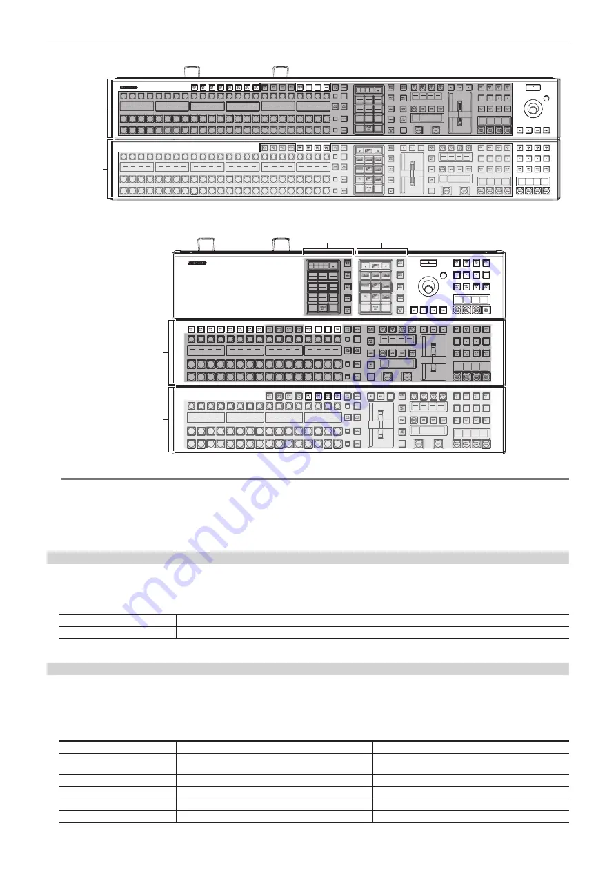
<AUX1/2> to <AUX15/16> buttons, <VMEM F/S> button, <DISP> button, <DSK1 F/S> to <DSK4 F/S> buttons, DSK operation area, positioner area,
and Menu Panel AV-HS60C3 are not subject for switching.
t
If you perform switching using the KEY bus selector buttons on the upper ME line (1st Line) while <AUX 1/2> to <AUX 15/16> buttons are selected,
the selection status of the KEY bus crosspoint buttons on the lower ME line (2nd Line) takes over the KEY bus crosspoint buttons on the upper ME
line (1st Line) before switching, and the KEY bus selector button lamps all turn off. Press the KEY bus selector buttons on the lower ME line (2nd Line)
to turn on the lamps and change the operation targets of the KEY bus crosspoint buttons to the appropriate bus.
Switching the ME area in the Menu Panel AV-HS60C3
1
Select the <PANEL> button
→
[PANEL CONFIG]
→
[ME Change] tab.
2
Select an item in [1st Line] and [2nd Line] in the [Panel1]/[Panel2]/[Panel3] column.
[ME1]
The corresponding ME area is used as ME1.
[ME2]
The corresponding ME area is used as ME2.
f
If the item set for [ME1] is switched to [ME2], the item selected for [ME2] is switched to [ME1].
Switching the ME area in multi-selection panel area
You can switch ME areas through the multi-selection panel area.
For basic operations of the multi-selection panel area, refer to “Basic operations for the multi-selection panel area”.
1
Press the <ME CHG> button.
f
The display of the multi-selection panel area changes as follows:
S1
Blank
―
S2
Current ME line
Displays the ME line to which the corresponding multi-
selection panel area belongs.
S3
Blank
―
1
ME1
The current ME line is displayed in red.
2
ME2
The current ME line is displayed in red.
3 to 12
Blank
―
Summary of Contents for Live Production Suite Series
Page 5: ...Please read this chapter and check the accessories before use Chapter 1 Overview ...
Page 11: ...This chapter describes installation and connection Chapter 2 Installation and Connection ...
Page 50: ...This chapter describes menu operations Chapter 5 Basic Operations ...
Page 113: ...This chapter describes the configuration of operations Chapter 7 Configuring Operations ...
Page 122: ...This chapter describes how to operate system menus Chapter 8 System Menu ...
Page 136: ...This chapter describes plug in functions Chapter 9 External Interfaces ...
Page 140: ... 140 Chapter 10 Specifications Dimensions Dimensions of the XPT Unit AV LSX10 Unit mm inch ...
Page 141: ... 141 Chapter 10 Specifications Dimensions Dimensions of the ME Unit AV LSM10 Unit mm inch ...
Page 153: ...This chapter describes the setting menu table and terms Chapter 11 Appendix ...
Page 176: ...Web Site https www panasonic com Panasonic Corporation 2020 ...

