– 173 –
Chapter 11 Appendix — Glossary
Glossary
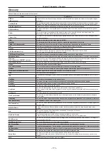
Defined below are the terms used in this manual.
Word
Explanation
AB Bus
AB Bus system
A bus control mode. By executing a transition, the A bus and B bus signals are output to the program images
alternately.
Ancillary Data
The auxiliary data other than the video signals, which is transmitted inside the data stream of the video serial
interface. The data superimposed on the vertical blanking period is referred to as the V ancillary data (VANC).
AUX (Auxiliary Bus)
A spare bus which can be switched by signals other than the main line output signals.
BB (BlackBurst)
The black burst signal. A composite signal of full-screen black level which is used as the reference signal for
Genlock.
Border
The area or margin that is added to the edge of a wipe or key. Its width and color can be adjusted. The
defocusing of the area around a border is referred to as the soft effect.
Chroma Key
This refers to the function for creating the key signals based on the color information of the video signals and
combining the keys.
Clip
Moving image memory of the video memory (VMEM)
Key Clip
The threshold level of the luminance when key signals are created from a key source.
CBGD (Color Background)
The signals which are output from the internal color generator and used as the background image.
Cut
This refers to the effect where the display is instantly switched to the next image.
Density
A parameter which is used to adjust the density of the key signals.
DSK (Downstream Key)
This refers to the key combination process which is performed at the end of the mix effect.
The key is always combined with the foremost image.
DVE (Digital Video Effect)
This refers to the transition patterns accompanying size reductions or slide effects.
Embedded Audio
This refers to the audio data packets which are transferred inside the data stream of the video serial interface.
Flip Flop
Flip Flop system (PGM/PST system)
A bus control mode. The signals selected by the program bus are always output as the program images. By
executing a transition, the program bus and preset bus signals are switched over.
Frame Synchronizer
The function which matches the synchronization of non-synchronized video input signals.
Freeze
The function which freezes the video signal.
FTB (Fade to Black)
This is the effect where the background image is faded out to the black screen.
Genlock
The function for synchronizing the video signals using an external sync signal as the reference.
GPI (General Purpose Interface)
Interface signals which control auto transition from an external source.
Hue
The color tone of the video signals.
IRE
A unit used for video signal levels. The setup level (black level) of the signals is expressed as 0 IRE, 7.5 IRE,
etc.
Key Edge
The border or shadow added to the edges of keys.
Key Fill
The signal that uses key composition processing to fill in the areas left blank by the key signals.
Key Gain
A parameter which is used to adjust the amplitude of the key signals.
Key Invert
The function which inverts the key signals.
Key Mask
The function that specifies the area for key composition using the box pattern, etc.
When only part of the area of the key signals is used, key composition is executed with the unnecessary area
masked.
Key Source
The video signals for creating the key signals.
Line Synchronizer
The function to automatically adjust the input video signal phase to the horizontal synchronization reference
signal phase.
Linear Key
The function which combines keys using monochrome key signals with gradations in its outlines as a reference.
Lum (Luminance)
The brightness portion of the video signals.
Luminance Key
The function which creates key signals based on the luminance (brightness) information of the video signals to
combine keys.
ME (Mix Effect)
A video effect device which combines a number of video signals to create mix, wipe, key and other video
signals.
Mix
The picture-changing effect produced by overlapping one image with the next.
It is also referred to as “dissolve”.
MultiView Display
This function combines multiple sources and displays them on one screen.
PGM, PVW, and the input source can be previewed at the same time on a single screen.
PVW (Preview)
The function for checking ahead of time the image which will be output after the next transition. The image is
output from the PVW line.
PGM (Program Bus)
The bus which always carries the program output signals.
PST (Preset Bus)
The bus which carries the program output signals after the next background transition.
RS-422
A serial interface standard. It is the interface used to control the switcher from an editor or other external device.
Sat (Saturation)
This refers to the saturation (intensity of the color chrominance level) of video signals.
Self Key
The function that creates key signals from key fill signals for combining keys.
Setup Data
The memory in which the control panel statuses can be saved and recalled.
The button selection statuses as well as the border, color and other setting information can be saved in this
memory.
Still
Still image memory of the video memory (VMEM).
Summary of Contents for Live Production Suite Series
Page 5: ...Please read this chapter and check the accessories before use Chapter 1 Overview ...
Page 11: ...This chapter describes installation and connection Chapter 2 Installation and Connection ...
Page 50: ...This chapter describes menu operations Chapter 5 Basic Operations ...
Page 113: ...This chapter describes the configuration of operations Chapter 7 Configuring Operations ...
Page 122: ...This chapter describes how to operate system menus Chapter 8 System Menu ...
Page 136: ...This chapter describes plug in functions Chapter 9 External Interfaces ...
Page 140: ... 140 Chapter 10 Specifications Dimensions Dimensions of the XPT Unit AV LSX10 Unit mm inch ...
Page 141: ... 141 Chapter 10 Specifications Dimensions Dimensions of the ME Unit AV LSM10 Unit mm inch ...
Page 153: ...This chapter describes the setting menu table and terms Chapter 11 Appendix ...
Page 176: ...Web Site https www panasonic com Panasonic Corporation 2020 ...

