– 24 –
Chapter 3 Part Names and Functions — Control Panel AV-HS60C2/AV-HS60C4
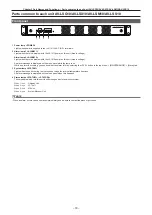
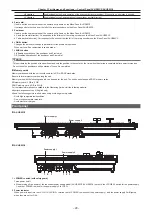
Crosspoint area
r
AV-HS60C2
4
SDI
IN3
3
SDI
IN2
2
SDI
IN1
1
Black
24
23
22
21
20
19
18
17
16
15
14
13
12
11
10
SDI
IN9
9
SDI
IN8
SDI
IN11
SDI
IN12
Still
1V
Still
2V
Still
3V
Still
4V
Clip
1V
Clip
2V
Clip
3V
Clip
4V
CBGD
1
ME1
PGM
ME2
PGM
SDI
IN10
8
SDI
IN7
7
SDI
IN6
6
SDI
IN5
5
SDI
IN4
BUS
SHFT
BUS
SHFT
4
SDI
IN3
3
SDI
IN2
2
SDI
IN1
1
Black
24
23
22
21
20
19
18
17
16
15
14
13
12
11
10
SDI
IN9
9
SDI
IN8
SDI
IN11
SDI
IN12
Still
1V
Still
2V
Still
3V
Still
4V
Clip
1V
Clip
2V
Clip
3V
Clip
4V
CBGD
1
ME1
PGM
ME2
PGM
SDI
IN10
8
SDI
IN7
7
SDI
IN6
6
SDI
IN5
5
SDI
IN4
1
2
3
4
5
6
7
8
1
r
AV-HS60C4
4
SDI
IN3
3
SDI
IN2
2
SDI
IN1
1
Black
16
15
14
13
12
11
10
SDI
IN9
9
SDI
IN8
SDI
IN11
SDI
IN12
Still
1V
Still
2V
Still
3V
SDI
IN10
8
SDI
IN7
7
SDI
IN6
6
SDI
IN5
5
SDI
IN4
BUS
SHFT
BUS
SHFT
4
SDI
IN3
3
SDI
IN2
2
SDI
IN1
1
Black
16
15
14
13
12
11
10
SDI
IN9
9
SDI
IN8
SDI
IN11
SDI
IN12
Still
1V
Still
2V
Still
3V
SDI
IN10
8
SDI
IN7
7
SDI
IN6
6
SDI
IN5
5
SDI
IN4
1
2
3
4
5
6
7
8
1
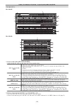
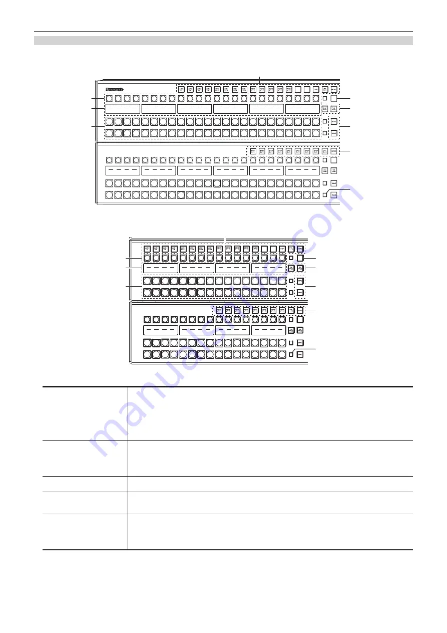
1 KEY bus selector buttons (KEY BUS DELEGATION)
Switches functions that can be operated using the KEY bus crosspoint buttons.
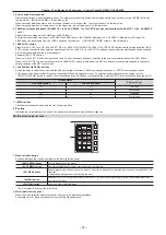
<AUX 1/2> to <AUX 15/16>
buttons
Switches to the source selector buttons for the AUX buses.
f
If you press the same buttons again while the <AUX 1/2> to <AUX 15/16> buttons are selected, the bus in the
background is selected.
Example)
If you press the <AUX 1/2> button again while the AUX1 bus is selected, the AUX2 bus is selected.
f
The <AUX 1/2> to <AUX 3/4> buttons have the MIX transition function. (page 119)
f
The <AUX 1/2> to <AUX 15/16> buttons have the crosspoint link coupling function. (page 117)
<KEY1 F/S> to <KEY4 F/S>
buttons
Switches to the source selector buttons for the key fill buses or key source buses.
f
If you select key fill signal or key source signal using the KEY bus crosspoint buttons, the signals are linked and
another signal is automatically selected. The unit’s linking operation has two modes. The mode setting can be made
from the <OPR> button on the top menu
→
[SOURCE LINK]
→
[Key Assign] tab
→
[Master/Slave]. The KEY3/KEY4
functions become the PinP1/PinP2 functions in the Live Production Suite.
<VMEM F/S> button
Switches to the source selector buttons for the fill buses or source buses of [CLIP1], [CLIP2] (video memory) and
[STILL1], [STILL2] (still image memory) input buses.
<MCRO> button
Switches to the start button to play back the macro memory assigned to the KEY bus crosspoint buttons. The
assignment can be made from the <MEM> button on the top menu
→
[MACRO]
→
[XPT Panel1] - [XPT Panel3] tab.
<DSK1 F/S> to <DSK4 F/S>
buttons
Switches to the source selector buttons for the DSK fill buses or DSK source buses.
f
If you select key fill signal or key source signal using the KEY bus crosspoint buttons, the signals are linked and
another signal is automatically selected. The unit’s linking operation has two modes. The mode setting can be made
from the <OPR> button on the top menu
→
[SOURCE LINK]
→
[Key Assign] tab
→
[Master/Slave]. The <DSK3 F/S>
and <DSK4 F/S> buttons cannot be used with the Live Production Suite.
2 KEY bus crosspoint buttons (AV-HS60C2: 1 to 24, AV-HS60C4: 1 to 16)
Selects the source of the bus which was selected by the KEY bus selector buttons.
Source can be selected using the <2nd PAGE>/<3rd PAGE> button. (AV-HS60C2: Maximum of 96, AV-HS60C4: Maximum of 64) (page 25)
Summary of Contents for Live Production Suite Series
Page 5: ...Please read this chapter and check the accessories before use Chapter 1 Overview ...
Page 11: ...This chapter describes installation and connection Chapter 2 Installation and Connection ...
Page 50: ...This chapter describes menu operations Chapter 5 Basic Operations ...
Page 113: ...This chapter describes the configuration of operations Chapter 7 Configuring Operations ...
Page 122: ...This chapter describes how to operate system menus Chapter 8 System Menu ...
Page 136: ...This chapter describes plug in functions Chapter 9 External Interfaces ...
Page 140: ... 140 Chapter 10 Specifications Dimensions Dimensions of the XPT Unit AV LSX10 Unit mm inch ...
Page 141: ... 141 Chapter 10 Specifications Dimensions Dimensions of the ME Unit AV LSM10 Unit mm inch ...
Page 153: ...This chapter describes the setting menu table and terms Chapter 11 Appendix ...
Page 176: ...Web Site https www panasonic com Panasonic Corporation 2020 ...

