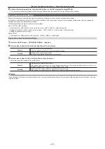
– 118 –
Chapter 7 Configuring Operations — Setting the operation mode
Setting the operation mode
Setting the operation mode for the crosspoint buttons
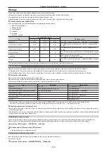
Selecting a bus using the SHIFT function
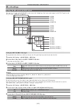
The SHIFT function is used to assign four sources to one crosspoint button (the KEY, PGM/A, or PST/B bus crosspoint button) and change pages using
the <2nd PAGE>/<3rd PAGE> buttons on the right of the source name display panel.
There are two operation methods for the SHIFT function:
All SHIFT
Use the <2nd PAGE>/<3rd PAGE> buttons to change all source pages for the crosspoint buttons included in the
corresponding ME at once.
Single SHIFT
Operate by assigning the <2nd PAGE>/<3rd PAGE> button to the crosspoint buttons with the menu.
Use the assigned button to change the source page of the crosspoint buttons included in the corresponding ME on a bus
basis. In this case, the <2nd PAGE>/<3rd PAGE> buttons on the right of the source name display panel can be used to
switch the source name displays.
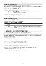
The <2nd PAGE>/<3rd PAGE> buttons can be used in two modes.
1
Select the <OPR> button
→
[OTHER SETTINGS]
→
[Page Mode] tab.
2
Set an item in [2nd Page Button] and [3rd Page Button] in the [Page Mode] column.
[Normal]
Enabled only while the button is pressed.
[Page Lock]
Enabled and disabled every time the button is pressed.
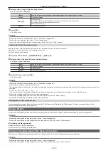
Assign the SHIFT function to the crosspoint buttons
1
Select the <PANEL> button
→
[XPT ASSIGN]
→
[Panel1]/[Panel2]/[Panel3] tab.
[Panel1] tab
Assigns the control panel 1.
[Panel2] tab
Assigns the control panel 2 (second Control Panel).
[Panel3] tab
Assigns the control panel 3 (third Control Panel).
2
Select the buttons to assign the SHIFT function from the button list in the left column.
f
3
Select [2nd Page] or [3rd Page] from the signal list in the right column.
f
[2nd Page] and [3rd Page] are displayed when [Special] is selected in [Page Select].
4
Select [Assign].
f
The SHIFT function is assigned to the button selected in the step
f
Once the assignment is set on one page, the corresponding button on other pages works in a same way.
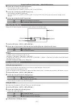
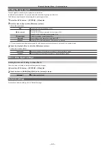
Selecting the bus mode
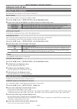
Select the A/B bus system or the flip-flop system (PGM/PST system).
1
Select the <OPR> button
→
[OTHER SETTINGS]
→
[Bus Mode] tab.
2
Set an item in [Bus Mode Type] in the [Bus Mode] column.
[Common]
Sets the same bus mode in ME1 and ME2.
Setting of the [Bus Mode] column
→
[Bus Mode] is applied to both ME1 and ME2.
[Each]
Different bus modes can be set for ME1 and ME2.
Settings of the [Each Bus Mode] column
→
[Bus Mode ME1] and [Bus Mode ME2] are applied to ME1 and ME2
respectively.
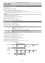
Setting the transition operation mode
Setting the time display unit
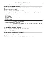
The time display unit used in this unit can be set as a second/frame basis or a frame basis.
1
Select the <OPR> button
→
[OTHER SETTINGS]
→
[Transition] tab.
2
Select an item in [Time Unit] in the [Time Unit] column.
[Sec/Frame]
Sets the time display unit as a second/frame basis.
[Frame]
Sets the time display unit as a frame basis.
f
The maximum possible setting time is 16s19f (499 frames).
Summary of Contents for Live Production Suite Series
Page 5: ...Please read this chapter and check the accessories before use Chapter 1 Overview ...
Page 11: ...This chapter describes installation and connection Chapter 2 Installation and Connection ...
Page 50: ...This chapter describes menu operations Chapter 5 Basic Operations ...
Page 113: ...This chapter describes the configuration of operations Chapter 7 Configuring Operations ...
Page 122: ...This chapter describes how to operate system menus Chapter 8 System Menu ...
Page 136: ...This chapter describes plug in functions Chapter 9 External Interfaces ...
Page 140: ... 140 Chapter 10 Specifications Dimensions Dimensions of the XPT Unit AV LSX10 Unit mm inch ...
Page 141: ... 141 Chapter 10 Specifications Dimensions Dimensions of the ME Unit AV LSM10 Unit mm inch ...
Page 153: ...This chapter describes the setting menu table and terms Chapter 11 Appendix ...
Page 176: ...Web Site https www panasonic com Panasonic Corporation 2020 ...


