– 47 –
Chapter 4 Preparations — Various settings
2
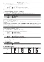
Turn on the power of the Control Panel AV-HS60C2/AV-HS60C4 while pressing the <KEY1> button, <KEY4> button, and <KEY1
TRNS> button in the KEY operation section of the ME line at the top.
The Control Panel AV-HS60C2/AV-HS60C4 is booted in the network setting mode.
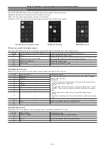
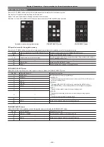
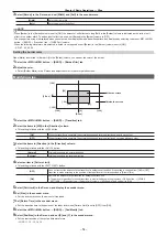
Part of the status display and the source display in the ME line at the top will become as follows when it goes into the network setting mode.
f
Status display: Setting item is displayed.
The setting item is switched every time the <AUTO> button in the ME line at the top is pressed.
Display
Setting item
Setting example
IP
IP address
192.168.0.8
MSK
Subnet mask
255.255.255.0
GTW
Default gateway
0.0.0.0
MIP
IP address of the connecting Live Production Suite system
192.168.0.90
f
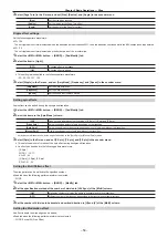
Source display: Setting value is displayed.
The value will increase by pressing the A bus XPT button under the setting value.
The value will decrease by pressing the B bus XPT button under the setting value.
3
Set each item.
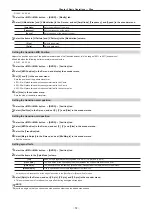
Change the setting value for each setting item, and confirm by pressing the <CUT> button in the ME line at the top.
f
The <CUT> button will light up in green when the setting is correctly made.
f
The <CUT> button will light up in red when the setting is not correctly made.
f
The changed setting value is not confirmed when the setting item is switched without pressing the <CUT> button.
f
When the value of the IP address is changed and the <CUT> button is pressed, the value is checked against the value of the subnet mask. At this
time, if the binary of the host address is changed to 0 or 1, the changed value is not confirmed. The <CUT> button lights up in red. In this case,
change the value of the subnet mask, and then change the value of the IP address.
4
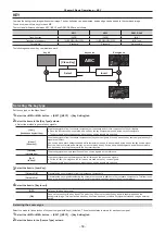
Turn off the power of the Control Panel AV-HS60C2/AV-HS60C4.
@
@
NOTE
t
For the subnet mask, use the same address as the address set for the <LAN> terminal of the Live Production Suite system.
t
Set the IP address that does not overlap with the following IP address.
- The IP address set to other device that is connected to the <LAN1> terminal of the Live Production Suite system
- The IP address set for the <LAN1> terminal of the Live Production Suite system
t
If the default setting for the <LAN1> terminal of the Live Production Suite system is not changed, it can be connected as the control panel 2/3 when
the value described in the setting example is set.
t
Configuring the network for the Live Production Suite system
Configure the network for the <LAN1> terminal of the Live Production Suite system.
f
The default setting is as follows: IP address: 192.168.0.90, subnet mask: 255.255.255.0, default gateway: No setting
1
Select the <SYS> button
→
[SYSTEM]
→
[Network] tab.
2
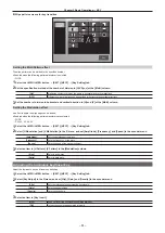
Set/check [IP Address] and [Subnet Mask] in the [Network] column.
[IP Address]
This can be changed from a web browser.
For details, contact your dealer.
[Subnet Mask]
This can be changed from a web browser.
For details, contact your dealer.
3
Check [Default Gateway] and [MAC Address] in the [Network] column.
[Default Gateway]
Checks the default gateway.
[MAC Address]
Checks the MAC address.
4
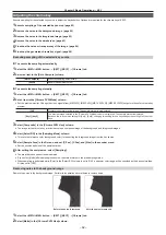
Select the <PANEL> button
→
[OTHER SETTINGS]
→
[Panel2] tab
→
[Network] column, and set the IP address of the control
panel 2 to be connected.
[IP Address]: Sets the IP address of the control panel 2 to be connected. (Setting example: 192.168.0.8)
Set this only when the control panel 2 is connected.
5
Select the <PANEL> button
→
[OTHER SETTINGS]
→
[Panel3] tab
→
[Network] column, and set the IP address of the control
panel 3 to be connected.
[IP Address]: Sets the IP address of the control panel 3 to be connected. (Setting example: 192.168.0.9)
Set this only when the control panel 3 is connected.
@
@
NOTE
t
To enable the settings, the system must be rebooted. Set the power to <OFF>, and then set it back to <ON>.
t
If you do not connect the control panel or computer to the <LAN1> terminal of the Live Production Suite system, it is not necessary to set up via the
menu.
t
If you use the device to be connected with the settings matching the default settings of the <LAN1> terminal of the Live Production Suite system, it is
not necessary to set up via the menu.
Summary of Contents for Live Production Suite Series
Page 5: ...Please read this chapter and check the accessories before use Chapter 1 Overview ...
Page 11: ...This chapter describes installation and connection Chapter 2 Installation and Connection ...
Page 50: ...This chapter describes menu operations Chapter 5 Basic Operations ...
Page 113: ...This chapter describes the configuration of operations Chapter 7 Configuring Operations ...
Page 122: ...This chapter describes how to operate system menus Chapter 8 System Menu ...
Page 136: ...This chapter describes plug in functions Chapter 9 External Interfaces ...
Page 140: ... 140 Chapter 10 Specifications Dimensions Dimensions of the XPT Unit AV LSX10 Unit mm inch ...
Page 141: ... 141 Chapter 10 Specifications Dimensions Dimensions of the ME Unit AV LSM10 Unit mm inch ...
Page 153: ...This chapter describes the setting menu table and terms Chapter 11 Appendix ...
Page 176: ...Web Site https www panasonic com Panasonic Corporation 2020 ...


