– 71 –
Chapter 5 Basic Operations — DSK (Downstream key)
DSK transition
Operating in the DSK operation area
r
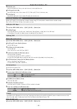
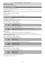
Operating the <DSK1 TRNS>, <DSK2 TRNS> buttons
Press the <DSK1 TRNS>, <DSK2 TRNS> buttons in the transition area to execute a transition automatically with the transition time of respective keys
set on the menu.
The <DSK1 TRNS>, <DSK2 TRNS> buttons flicker during key in, and light when the transition is complete. If the <DSK1 TRNS>, <DSK2 TRNS>
buttons are pressed while key in is complete, transition of the key image (key out) is executed.
The <DSK1 TRNS>, <DSK2 TRNS> buttons light during key out, and go off when the transition is complete. If the <DSK1 TRNS>, <DSK2 TRNS>
buttons are pressed during the transition, the transition direction is reversed.
r
Operating the <DSK1 ON>, <DSK2 ON> buttons
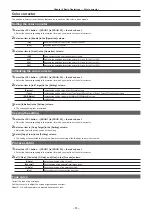
Press the <DSK1 ON>, <DSK2 ON> buttons to turn on/off respective DSK with the cut transition.
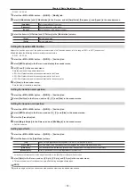
Setting the DSK transition mode
Transition mode and transition time can be set separately for key in and key out.
1
Select the <DSK> button
→
[DSK1], [DSK2]
→
[Transition] tab.
2
Select an item in [Transition] in the [In Type]/[Out Type] column.
f
The transition mode available is only [MIX].
[Off]
Disables the transition mode of key in or key out.
[On]
Enables the transition mode of key in or key out.
3
Set [Time] in the [In Type]/[Out Type] column.
f
Set the transition time.
4
Select an item in [In=Out] in the [Out Type] column.
[Off]
Sets the [In Type] column and the [Out Type] column separately.
[On]
The [In Type] column setting becomes the same as the [Out Type] column setting.
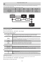
DSK output
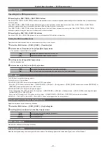
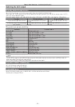
The DSK block outputs the following signals.
For details, refer to “System Menu”.
f
DSKPGM1, DSKPGM2: Outputs program signals of DSK compositions.
Select the <SYS> button on the top menu
→
[MAIN FRAME]
→
[DSK] tab
→
[Config] column
→
[DSK1], [DSK2] and set them to either [DSKPGM1] or
[DSKPGM2] to assign the signal to one of the outputs.
f
DSKPVW1, DSKPVW2: Outputs DSK preview signals.
Follow the setting of the <SYS> button on the top menu
→
[MAIN FRAME]
→
[DSK] tab
→
[Config] column
→
[DSK1], [DSK2], and assign the signal
to either DSKPVW1 or DSKPVW2 line.
Keyers set to [Off] using the <SYS> button on the top menu
→
[MAIN FRAME]
→
[DSK] tab
→
[DSK PVW] column are not combined.
f
DSK EXT1-1, DSK EXT1-2, DSK EXT2-1, DSK EXT2-2: These output signals can be set by the user.
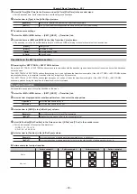
Adjusting the luminance key/linear key
Adjust the luminance key and linear key definition.
1
Select the <DSK> button
→
[DSK1], [DSK2]
→
[Key Setting] tab.
2
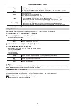
Set [Clip], [Gain], and [Density] in the [Key Adjust] column.
[Clip]
Sets the reference level for creating key signals.
[Gain]
Sets the key amplitude.
[Density]
Sets the key density.
DSK decorations
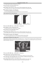
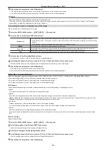
Add a border, shadow, or other edge to the key.
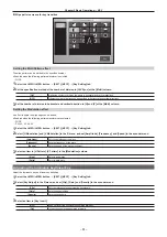
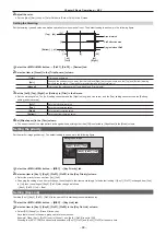
Masking the DSK
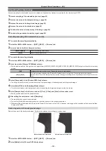
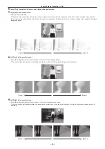
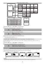
Mask the key signals using the mask signal of the box pattern. The following figure is the status when [Type] is set to [ForeGround].
Summary of Contents for Live Production Suite Series
Page 5: ...Please read this chapter and check the accessories before use Chapter 1 Overview ...
Page 11: ...This chapter describes installation and connection Chapter 2 Installation and Connection ...
Page 50: ...This chapter describes menu operations Chapter 5 Basic Operations ...
Page 113: ...This chapter describes the configuration of operations Chapter 7 Configuring Operations ...
Page 122: ...This chapter describes how to operate system menus Chapter 8 System Menu ...
Page 136: ...This chapter describes plug in functions Chapter 9 External Interfaces ...
Page 140: ... 140 Chapter 10 Specifications Dimensions Dimensions of the XPT Unit AV LSX10 Unit mm inch ...
Page 141: ... 141 Chapter 10 Specifications Dimensions Dimensions of the ME Unit AV LSM10 Unit mm inch ...
Page 153: ...This chapter describes the setting menu table and terms Chapter 11 Appendix ...
Page 176: ...Web Site https www panasonic com Panasonic Corporation 2020 ...

