174
■
Response Data
There are three types of the response data the laser marker sends back against the command data sent from
the external device as follows.
1. Normal reception response data
The start code of this response data is started with “ACK”. If the command is normal, or if the command
processing is ended normally, this response data is sent back.
2. Abnormal reception response data
The start code of this response data is started with “NAK”. If the command is abnormal, or if the command pro-
cessing is ended abnormally, this response data is sent back.
3. Readout data
The start code of this data is started with “STX”. If the command is normal and the subcommand is
expressed with ‘R’, this response data is sent back.
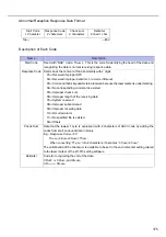
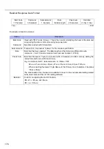
Normal Reception Response Data Format
Description of Each Code
Name
Description
Start Code
Fixed with “ACK” (code: 06
(HEX)
). This is the code for identifying the head of the data and
recognizing the data is normal receiving response data.
Response Code Sends back 2 characters ‘00’ for ACK.
Check Sum
Data that the lowest 1 byte is expressed with 2 characters of ASCII code by adding the
codes from start code until data in binary
E.g.: 06
(HEX)
+30
(HEX)
+30
(HEX)
=66
(HEX)
When converting ‘66
(HEX)
’ into 2 characters, it becomes “36
(HEX)
+36
(HEX)
”.
The valid/invalid of the checksum is available to be set in the environmental setting related
to the laser marker of the LP-310 setting software.
Delimiter
Code for recognizing the end of the data
CR+LF ••• 0D
(HEX)
and 0A
(HEX)
CR •••••••
0D
(HEX)
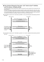
Start Code
1 Character
Response Code
2 characters
Check sum
2 characters
Delimiter
2 char./1 char.
Top
←
→
End
Summary of Contents for LP-310
Page 5: ...5 MEMO ...
Page 21: ...21 MEMO ...
Page 26: ...26 MEMO ...
Page 30: ...30 MEMO ...
Page 33: ...33 MEMO ...
Page 87: ...87 MEMO ...
Page 125: ...125 MEMO ...
Page 137: ...137 MEMO ...
Page 149: ...149 MEMO ...
Page 155: ...155 4 External Control 4 1 Control Through I O Connector 156 4 2 Control with RS 232C 166 ...
Page 186: ...186 MEMO ...
Page 187: ...187 5 Troubleshooting 5 1 Troubleshooting 188 5 2 Measures for Indicated Error 189 ...
Page 191: ...191 6 Maintenance 6 1 Maintenance 192 ...
Page 193: ...193 7 Specification 7 1 Specification 194 7 2 Outer Dimensional Drawing 195 ...
Page 197: ...197 Appendix Character Code Table 198 Readable DXF File 207 Glossary 209 ...
Page 212: ...212 Index Index 213 ...
Page 215: ...No 9000 0062 20V ...


