179
■
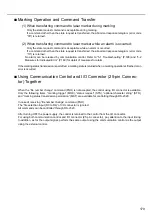
Marking Operation and Command Transfer
(1) When transferring command to laser marker during marking:
Only the state request command is acceptable during marking.
If a command other than the state request is transferred, the abnormal response telegram (error code
“03”) is returned.
(2) When transferring command to laser marker while an alarm is occurred:
Only the state request command is acceptable while an alarm is occurred.
If a command other than the state request is transferred, the abnormal response telegram (error code
“10”) is returned.
No alarm can be released by communication control. Refer to “5-1 Troubleshooting” (P.188) and “5-2
Measures for Indicated Error” (P.189) for detail of measures for alarm.
If the marking status transmission is permitted, a marking state is returned when a marking operation is finished or an
error is occurred.
■
Using Communication Control and I/O Connector (25-pin Connec-
tor) Together
When the “file number change” command (FNO) is not accepted, the control using I/O connector is available.
Only the following items, “marking trigger” (MRK), “status request” (STS), “optional character string” (STR),
and “marking status transmission permission” (MST) are available for controlling through RS-232C.
In case of receiving “file number change” command (FNO):
The “file selection input (D0 to D6)” of I/O connector is ignored.
All commands can be controlled through RS-232C.
After turning OFF the power supply, the control is returned to the control from the I/O connector.
For using both communication control and I/O connector (25-pin connector), pay attention to the input timing.
In addition, as for the output signal, perform the same output using the communication control as the output
using the external control.
Summary of Contents for LP-310
Page 5: ...5 MEMO ...
Page 21: ...21 MEMO ...
Page 26: ...26 MEMO ...
Page 30: ...30 MEMO ...
Page 33: ...33 MEMO ...
Page 87: ...87 MEMO ...
Page 125: ...125 MEMO ...
Page 137: ...137 MEMO ...
Page 149: ...149 MEMO ...
Page 155: ...155 4 External Control 4 1 Control Through I O Connector 156 4 2 Control with RS 232C 166 ...
Page 186: ...186 MEMO ...
Page 187: ...187 5 Troubleshooting 5 1 Troubleshooting 188 5 2 Measures for Indicated Error 189 ...
Page 191: ...191 6 Maintenance 6 1 Maintenance 192 ...
Page 193: ...193 7 Specification 7 1 Specification 194 7 2 Outer Dimensional Drawing 195 ...
Page 197: ...197 Appendix Character Code Table 198 Readable DXF File 207 Glossary 209 ...
Page 212: ...212 Index Index 213 ...
Page 215: ...No 9000 0062 20V ...

