196
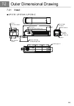
7-2-2 Power Supply BOX
■
LP-310/ LP-310-A
■
LP-310-C
35
140
57.5
200
30
255
12.5
70
210
(12.5)
315
(4)
95
Key Switch
Main Power
Indicator
Cooling Fan
Interlock Connector
FG
Inlet
Power
Supply
Connector
FUSE
4-M4X0.7 depth 10
4-M4X0.7 depth 10
CO Laser Marker
series
POWER
LP-300
2
(12.5)
140
57.5
255
200
70
12.5
35
30
315
210
(14.5)
95
Key Switch
Main Power
Indicator
Cooling Fan
Interlock
Connector
FG
Inlet
Power
Supply
Connector
FUSE
4-M4X0.7 depth 10
4-M4X0.7 depth 10
Summary of Contents for LP-310
Page 5: ...5 MEMO ...
Page 21: ...21 MEMO ...
Page 26: ...26 MEMO ...
Page 30: ...30 MEMO ...
Page 33: ...33 MEMO ...
Page 87: ...87 MEMO ...
Page 125: ...125 MEMO ...
Page 137: ...137 MEMO ...
Page 149: ...149 MEMO ...
Page 155: ...155 4 External Control 4 1 Control Through I O Connector 156 4 2 Control with RS 232C 166 ...
Page 186: ...186 MEMO ...
Page 187: ...187 5 Troubleshooting 5 1 Troubleshooting 188 5 2 Measures for Indicated Error 189 ...
Page 191: ...191 6 Maintenance 6 1 Maintenance 192 ...
Page 193: ...193 7 Specification 7 1 Specification 194 7 2 Outer Dimensional Drawing 195 ...
Page 197: ...197 Appendix Character Code Table 198 Readable DXF File 207 Glossary 209 ...
Page 212: ...212 Index Index 213 ...
Page 215: ...No 9000 0062 20V ...


