213
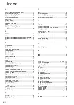
Index
A
Abnormal Reception Response Data Format
.............................. 175
Adjustment of Display Position
................................................... 133
Adjustment of Laser Start/End Points
......................................... 128
Adjustment of Marking Position
.................................................. 132
Adjustment of Marking Quality
.................................................... 129
Air Filter
..................................................................................... 192
Alarm Output
............................................................................. 163
Ambient humidity
......................................................................... 16
Ambient temperature
.................................................................... 16
Appearance of Connector
.......................................................... 157
Appendix
................................................................................... 197
Appointment of laser safety manager
.............................................. 9
Arbitrary character string (code
STR)................................................................................. 182
B
BACKUP
................................................................................... 142
Basic I/O
.................................................................................... 164
battery
......................................................................................... 19
Before External Controlling Laser Marker Using I/O Connector
.... 156
Before External Controlling Laser Marker Using RS-232C
........... 166
Bold
........................................................................................... 119
C
CAD Condition
........................................................................... 120
CAD file
..................................................................................... 121
Cautions in Handling
.................................................................... 15
Cautions in Handling Laser Beam
................................................... 6
Center of Marking
........................................................................ 38
Center Position Indication
.......................................................... 134
Character array
.......................................................................... 194
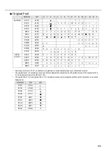
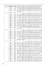
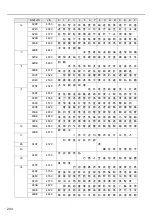
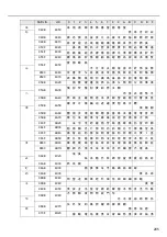
Character Code Table
................................................................ 198
Character Condition
................................................................... 115
Character Setting Screen
............................................................. 88
Character type
........................................................................... 194
Check Connection
..................................................................... 169
Clock
......................................................................................... 150
Command Data
......................................................................... 173
Command Data Format
.............................................................. 173
Communication Command and Function
.................................... 180
Communication Data Format
...................................................... 173
Communication Port
.................................................................. 151
Communication Sequence
......................................................... 177
Connecting Head and Power Supply BOX
.................................... 40
Connecting Laser Marker
............................................................. 40
Connecting Laser Marker and Personal Computer
........................ 41
Connecting Sample
...................................................................... 13
Connecting Sample (In case of operating laser marker standalone)
Construction of Main Screen
........................................................ 78
Construction of Manual
................................................................ 27
Construction Sample of Interlock System
...................................... 14
Contamination of f-theta Lens
..................................................... 192
Control Through I/O Connector
................................................... 156
Control with RS-232C
................................................................ 166
Counter current value (code
CNT)................................................................................. 183
Counter Ending Output
.............................................................. 163
Counter reset (code
CTR)................................................................................. 183
Counter Reset Input
................................................................... 162
D
Delimiter
.................................................................................... 180
Description of Main Screen
.......................................................... 76
Details of Commands
................................................................. 180
E
Edit
.............................................................................................. 79
Environmental humidity
.............................................................. 194
Environmental Setting
................................................................ 150
Environmental Setting Related to Laser Marker
.......................... 150
Environmental Setting Related to PC
.......................................... 152
Environmental temperature
........................................................ 194
F
File
.............................................................................................. 79
FILE LIST
.................................................................................. 142
File No./Error Code Display
.......................................................... 10
File No./Error Code Display (Head display panel)
.......................... 34
File number change (code
FNO)................................................................................. 180
File Select Input (D0 to D6)
........................................................ 162
FILE TRANSMIT
........................................................................ 140
Font
........................................................................................... 122
Font File
.................................................................................... 153
Frame Ground
F.G. .................................................................................... 35
Function Setting Screen
............................................................. 104
Functions for Safety Measures
..................................................... 10
Fuse
............................................................................................ 35
G
Guide Indication
......................................................................... 134
Guide Laser Function
................................................................... 39
H
Handle
......................................................................................... 34
Head
........................................................................................... 34
Help
............................................................................................ 80
I
I/O Connector
......................................................... 13
I/O Connector Input Signal
......................................................... 162
I/O Connector Output Signal
....................................................... 163
Image Display Screen
................................................................ 130
Inlet
............................................................................................. 35
Input Circuit
............................................................................... 160
Input Common
........................................................................... 162
Input Connecting Sample
........................................................... 160
Input counter
............................................................................... 96
Input current date
......................................................................... 90
Input date function character
........................................................ 72
Input expiry date
.......................................................................... 93
Input lot
....................................................................................... 98
Input of Marking Character
........................................................... 89
Input optional character string
.................................................... 100
Input Rating
............................................................................... 160
Input registration character
......................................................... 102
Input the character to be marked.
................................................. 49
Input the counter function character.
............................................. 60
Input the lot function character.
..................................................... 64
Input/Output Operation
............................................................... 162
Installation Direction
..................................................................... 37
Installation Method
....................................................................... 36
Installation Space
........................................................................ 38
Interlock Connector
.............................................................12
K
Key Switch
..........................................................................12
Summary of Contents for LP-310
Page 5: ...5 MEMO ...
Page 21: ...21 MEMO ...
Page 26: ...26 MEMO ...
Page 30: ...30 MEMO ...
Page 33: ...33 MEMO ...
Page 87: ...87 MEMO ...
Page 125: ...125 MEMO ...
Page 137: ...137 MEMO ...
Page 149: ...149 MEMO ...
Page 155: ...155 4 External Control 4 1 Control Through I O Connector 156 4 2 Control with RS 232C 166 ...
Page 186: ...186 MEMO ...
Page 187: ...187 5 Troubleshooting 5 1 Troubleshooting 188 5 2 Measures for Indicated Error 189 ...
Page 191: ...191 6 Maintenance 6 1 Maintenance 192 ...
Page 193: ...193 7 Specification 7 1 Specification 194 7 2 Outer Dimensional Drawing 195 ...
Page 197: ...197 Appendix Character Code Table 198 Readable DXF File 207 Glossary 209 ...
Page 212: ...212 Index Index 213 ...
Page 215: ...No 9000 0062 20V ...

