34
1-2
Name of Each Part
1-2-1 Head
1. Laser Radiation Indicator
This indicator indicates the laser radiation state. (Refer to “Functions for Safety Measures” (P.10) for details.)
• Lights up in blue: Indicates while the power supply is ON.
• Lights up in red: Indicates the marking laser is radiated. Also this indicator flashes for 0.5 seconds just after
turning on the power supply.
2. File No./Error Code Display (Head display panel)
The error code is displayed while there exists the file No. under marking and while an error is occurred.
• Rotation Display: Indicates the marking laser is under excitation.
• Normal
: Indicates the file No. under marking.
• Under Error
: Indicates the error code starting from the character “E”. (Refer to “5-2 Measures for Indi-
cated Error” (P.189) for details.)
3. Shutter Lever (Guide Indication Switching Lever)
This shutter lever is used as the external shutter, and also is activated as the switching lever switching
between guide indication laser and marking laser.
• OPEN : Set when radiating marking laser. Invalid for using guide laser.
• CLOSE : Blocks radiation of the marking laser. Indicates that the laser marker is in guide laser radiation
state.
4. Power Connector
This is the connector for supplying power to the head. Connect the attached head power cable.
5. I/O Connector
This connector is used for controlling the head from external device. Connect the attached I/O connector.
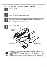
To operate this laser marker, connect the following signals on I/O connector. For the details, refer to “4-1-2 I/O
Connector” (P.157).
• Connect the power supply to [IN COM.] (pin No.14) and to [OUT COM.] (pin No.15) respectively.
• Connect [LASER STOP] (pin No.4) and [OUT COM.] (pin No.15) to release the laser stop function.
6. USB Connector
This connector is used when the data set on the PC is required transferring to the laser marker itself.
7. RS-232C Connector
This RS-232C connector is used for controlling the laser marker using the communication from the external
device.
8. Handle
This part can be used for carrying the head of the laser marker. This product can be carried with both hands
using this handle and the uneven part on the front side.
9. Radiation Nozzle of Laser and Guide Laser
This is the part from which the marking laser and guide laser are radiated. Do not block off the radiation nozzle
when installing this product.
Also, this part is manufactured with f
θ
lens.
w
q
e
t
i
o
y u
r
2
1
3
4
5
9
8
6 7
Summary of Contents for LP-310
Page 5: ...5 MEMO ...
Page 21: ...21 MEMO ...
Page 26: ...26 MEMO ...
Page 30: ...30 MEMO ...
Page 33: ...33 MEMO ...
Page 87: ...87 MEMO ...
Page 125: ...125 MEMO ...
Page 137: ...137 MEMO ...
Page 149: ...149 MEMO ...
Page 155: ...155 4 External Control 4 1 Control Through I O Connector 156 4 2 Control with RS 232C 166 ...
Page 186: ...186 MEMO ...
Page 187: ...187 5 Troubleshooting 5 1 Troubleshooting 188 5 2 Measures for Indicated Error 189 ...
Page 191: ...191 6 Maintenance 6 1 Maintenance 192 ...
Page 193: ...193 7 Specification 7 1 Specification 194 7 2 Outer Dimensional Drawing 195 ...
Page 197: ...197 Appendix Character Code Table 198 Readable DXF File 207 Glossary 209 ...
Page 212: ...212 Index Index 213 ...
Page 215: ...No 9000 0062 20V ...


