background image

71

2-2-4 Mark Current Date

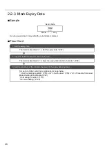
Sample

This section describes the procedure for setting the current time.

Flow of Procedure

12   :   30

Hour

Minute

1. Input the function character of the date.

The detail is described in “ a. Input date function character.” (P.72)

2. Set the conditions of the function character of the date and laser.

Set each condition referring to relative item shown below:
“ 3. Set the marking condition.” (P.50)  and “ 4. Set the laser.” (P.53) in “2-1-3 Procedure from Laser
Marker Setting to Test Marking”
“3-5 Marking Condition” (P.110)
“3-6 Laser Setting” (P.126)

Summary of Contents for LP-310

Page 1: ...表紙 はじめに CO2 Laser Marker LP 300 SERIES Operation Manual panasonic net id pidsx global 2018 5 ME LP300 OP 12 No 9000 0062 20V ...

Page 2: ...r comments in this manual please notify us 4 Please remind that we do not have responsibility of any results of operations in regardless of the above 3 clauses DANGER denotes hazards that could result in serious personnel injury or death when handling error occurs and emergency precautions urgency level when any dangerous situation causes WARNING denotes hazards that could result in serious person...

Page 3: ... OF MERCHANTABILITY FITNESS FOR A PARTICULAR PURPOSE AND NON INFRINGEMENT OF PROPRIETARY RIGHTS ARE HEREBY EXPRESSLY DISCLAIMED IN NO EVENT SHALL Panasonic Indus trial Devices SUNX AND ITS AFFILIATED ENTITIES BE LIABLE FOR DAMAGES IN EXCESS OF THE PURCHASE PRICE OF THE PRODUCTS OR FOR ANY INDIRECT INCIDENTAL SPECIAL OR CONSEQUENTIAL DAMAGES OF ANY KIND OR ANY DAMAGES RESULTING FROM LOSS OF USE BUS...

Page 4: ...of the failure parts of the system or repair of it is performed in the responsibility of the supplier However if failure of the system has resulted from the following reasons the warranty is void 1 Any fault or defect caused by inadequate handling or abnormal use 2 Any fault or defect caused by the other reasons than the supplier s fault 3 Any fault or defect caused by modification or repair of th...

Page 5: ...5 MEMO ...

Page 6: ... NOHD represents the distance from the light source of laser beam where the amount of beam irradiance or radiant expposure is equal to the maximum permissible exposure to eyes 3 MPE means the assumed exposure duration for determination of the value The value colculated on 10 seconds Laser Radiation Range Unit mm Item Specification Remarks Wave Length 10 6μm Invisible beam Laser Medium CO2 Max Outp...

Page 7: ...ator s eyes The goggles should be used against scattered beam so avoid to direct beam or reflection beam In order to prevent unexpected exposures from object to be marked or its peripherals set protective enclosure which is made of acrylic resin glass or metal to enclose the laser radiation area Never disassemble the product Exposure of laser beam or electric shock by high voltage area might occur...

Page 8: ...r to prevent exposure to laser beam accidentally reflected from the laser marking object or from its circumferential areas place a protective enclosure so that it can enclose the area in the range of laser radiation Construct the enclosure with proper reflectance durability and thermal resistance materials that does not transmit a wavelength of 10600 nm 10 6 μm Recommended materials for the enclos...

Page 9: ...lit place it reduces the risk to the eyes 10 Protective clothing Exposure of the skin to the laser beam may cause a skin burn Exposure of the clothing to the laser beam may cause burning as well Wear the clothing which can minimize the exposure of the skin to the laser and which is flame resistant 11 Appointment of laser safety manager By appointing a laser safety manager ensure that the laser pro...

Page 10: ... lights in red for 0 5 seconds just after the power supply is turned ON Then it lights in blue during trigger standby The color of the indicator is changed into red during marking 3 File No Error Code Display FILE No ERROR CODE The selected file No is displayed When an error occurs the corresponding error code is displayed as well Refer to 5 Troubleshooting P 187 for details of error code During e...

Page 11: ...lanatory aperture label Protection Housing Label LP 310 A LP 310 C Warning explanatory aperture label Protection Housing Label Certification and identification label 1 1 Attached to LP 310 A only Warning explanatory aperture label Protection Housing Label Certification and identification label 1 Head rear side ...

Page 12: ... Interlock Connector This interlock connector controls the deactivating activating status of the laser It enables to construct the interlock system Interlock Connector This product is equipped with the interlock connector to the power supply box Use this interlock connector Interlock Connector SRCN6A13 3P Japan Aviation Electronics Industry Ltd Connector on the body side SRCN2A13 3S Japan Aviation...

Page 13: ...ser radiation is stopped and the marking is invalid When performing marking connect both laser radiation stop input Pin 4 and output common Pin 15 Connecting Sample In case of operating only laser marker Example when only the file No 1 is used To change the files connect the pin No 5 to 8 and 18 to 20 D0 to D6 to the external control device This product is not activated by connecting Pin 14 Pin 15...

Page 14: ...us of Interlock Input Shutter Laser Oscillation Marking Operation Laser Radiation Indicator Laser Marker Status Head display panel Short circuit OPEN ON Red Normal Operation File No OFF Blue CLOSE OFF Blue Release OPEN OFF Blue Alarm Status Error Code CLOSE Release Short circuit OPEN OFF Blue Ready OFF after 15 sec Ready ON Error Code after 15 sec File No CLOSE Ready OFF Short circuit Release Rele...

Page 15: ...them or adhering them to skin be sure to wear glove mask and protective goggles When disposing the lens be sure to obey the disposing method prescribed in the regulations of user s region countryfully Do not dispose the lens with general industrial waste Do not throw the lens into the fire Do not soak the lens in acid and alkali Never disassemble the product It can result in exposure to laser radi...

Page 16: ...ondensation The air cooling system is used for this product as a laser cooling system Please install not to bar the flow of air cooling Moreover please do not install a heat source in near either Since this product includes precision parts please avoid vibration and use in a place with any shocks Printing quality may deteriorate or the optical system may be affected Moreover please do not drop thi...

Page 17: ...re Clean air filter when it is dirty with dust etc If the air filter is dirty the air flow might become bad and might stop marking operation Exchange air filter periodically While marking is carried out dust and or gas may be produced from the place to be marked Always ventilate and remove them using a dust collector etc Not collecting dust may affect the marking quality badly When the laser marke...

Page 18: ...wer 8 Note that the marked characters may be blurred if a CD cleaner or other liquid gets on the marked surface of the attached CD ROM LP 310 Setting Software Model Applicable standards and regulations LP 310 JIS Japanese Industrial Standards JIS C 6802 2014 Safety of laser products LP 310 A FDA Food and Drug Administration Regulations 21 CFR1040 10 and 1040 11 except for deviations pursuant to La...

Page 19: ...ackaging and or accompanying documents mean that used electri cal and electronic products and batteries must not be mixed with general household waste For proper treatment recovery and recycling of old products and batteries please take them to applica ble collection points in accordance with your national legislation By disposing of them correctly you will help to save valuable resources and prev...

Page 20: ...used for enhansing the installation of the battery to the board using the nipper Then cut the terminal of the battery one by one and remove the battery from the board When detaching the used battery be sure to disconnect the power cable so that the power shall not be supplied to the device This method is never described with the replacing method of the battery The battery is replaced by our servic...

Page 21: ...21 MEMO ...

Page 22: ...1 1 5 Connecting with External Device 42 1 5 1 Operation Sample Using External Control Device 42 1 5 2 Operation Procedure Using External Control 43 1 5 3 Shift to Remote Mode 44 2 Basic Operation Procedure 45 2 1 When Using Laser Marker for the First Time 46 2 1 1 Preparation of Laser Marker Operation 47 2 1 2 Startup of Laser Marker 48 2 1 3 Procedure from Laser Marker Setting to Test Marking 49...

Page 23: ...eral Conditions 111 3 5 3 Character Condition 115 3 5 4 CAD Condition 120 3 5 5 Laser Check 124 3 6 Laser Setting 126 3 6 1 Screen for Laser Setting 126 3 6 2 Line Width 127 3 6 3 Marking Pitch 127 3 6 4 Adjustment of Laser Start End Points 128 3 6 5 Adjustment of Marking Quality 129 3 7 Image Display 130 3 7 1 Image Display Screen 130 3 7 2 Magnification Method 131 3 7 3 Adjustment of Marking Pos...

Page 24: ...1 4 1 6 Input Output Operation 162 4 1 7 Timing Chart 164 4 2 Control with RS 232C 166 4 2 1 Before External Controlling Laser Marker Using RS 232C 166 4 2 2 RS 232C Connector 167 4 2 3 Specification for RS 232C 167 4 2 4 Setting of Communication Condition 168 4 2 5 Connecting Sample of External Control Device 168 4 2 6 Check Connection 169 4 2 7 Sample of Control 170 4 2 8 Communication Data Form...

Page 25: ...25 7 2 2 Power Supply BOX 196 Appendix 197 Character Code Table 198 Readable DXF File 207 Glossary 209 Index 212 Index 213 ...

Page 26: ...26 MEMO ...

Page 27: ...ing the laser marker such as the setting character to be marked and the function for marking P 75 This chapter describes the connecting method to the external control devices such as PLC device using external power supply Read this chapter when connecting this product to the external device P 155 This chapter describes the error messages and measures Read this chapter when error message is appeare...

Page 28: ...ts of what user tries to do are described using this Let s Try Contents 2020 3 20 Expiry Date Expiry Date January February December 0001 0002 0003 0004 Connecting Laser Marker P 40 Setting of Expiry Date Function P 105 Input expiry date P 93 Input current date P 90 Install Installation Manual Setting of Counter Function P 106 Input counter P 96 Setting of Lot Function P 107 Input lot P 98 Installa...

Page 29: ...ter Height Start Radius Line Interval Radius Character Width Character Interval Angle Start Angle Troubleshooting P 188 Measures for Indicated Error P 189 Control Through I O Connector P 156 ABCD CAD Condition P 120 Character Condition P 115 Control with RS 232C P 166 Communication Command and Function P 180 Details of Commands P 180 ABC PLC ABC Personal Computer ...

Page 30: ...30 MEMO ...

Page 31: ...31 1 Preparation 1 1 Package Check 32 1 2 Name of Each Part 34 1 3 Installation 36 1 4 Connecting Laser Marker 40 1 5 Connecting with External Device 42 ...

Page 32: ...on Manual Japanese English Chinese Be sure to store the packing material Since this product is delicate one apply the packing material that is used for this product for preventing from the failure caused by transferring Head 1 Power Supply BOX 1 Installation Manual for Setting Software 1 Operation Manual this manual 1 Power Cable for Head 1 AC Power Cable 1 1 USB Cable 1 I O Connector 1 I O Connec...

Page 33: ...33 MEMO ...

Page 34: ...cates that the laser marker is in guide laser radiation state 4 Power Connector This is the connector for supplying power to the head Connect the attached head power cable 5 I O Connector This connector is used for controlling the head from external device Connect the attached I O connector To operate this laser marker connect the following signals on I O connector For the details refer to 4 1 2 I...

Page 35: ... Opening both Pin 1 and Pin 3 stops the power and connecting these pins supplies power 4 Frame Ground F G This is the terminal for grounding Be sure to ground this product either by this terminal or earth terminal of the inlet 5 Inlet With this inlet the AC power supply is connected Use the attached AC power cable 90V to 132V AC or 180V to 264V AC including 10 voltage fluctuations 50 60Hz Voltage ...

Page 36: ...from the bottom with M4 screw at four locations The inserting length of the screw shall be 10mm or less The tightening torque shall be 2 0N m or less The inserting length of the screw shall be 10mm or less Note that the inserting length of the screw on side surface of LP 310 C shall be 5mm or less The tightening torque shall be 2 0N m or less CHECK 30 35 140 4 M4 4 M4 70 200 57 5 12 5 255 CHECK ...

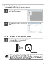
Page 37: ...making use of the laser marker safely and fully install the laser marker in either direction shown below Head Power Supply BOX Do not incorporate the laser marker in a unit where the laser head will be moved It may cause failure CHECK ...

Page 38: ...ooling are equipped Make space around the product as shown in the following figure Head Power Supply BOX 1 3 2 Center of Marking 15cm以上 15cm以上 15cm以上 15cm以上 20cm以上 15cm以上 Min 15cm Min 15cm Min 15cm Min 20cm Min 15cm Min 15cm 145 78 50 Marking Position 50 200 16 Screw hole for fixing Marking Area 50mmX50mm ...

Page 39: ...nction The marking contents and marking area can be traced with the red guide laser By using the guide laser function the position adjustment of the marking is available easily Refer to 3 8 Guide Indication P 134 for details of the operating method ABCD ABCD ...

Page 40: ...able away from the device that generates high voltage power line and large switching surge as far as possible 4 If any noise is occurred on the power source use the noise cut off transducer 5 Be sure to ground the F G frame ground terminal Refer to 1 2 2 Power Supply BOX P 35 for the terminal position 6 Fix the connector with screws securely so as not to drop it 7 To operate this laser marker conn...

Page 41: ...ker and Personal Computer Connect the following items using the attached specific cables The function that several LP 310s are operated with only one personal computer is not incorporated Head Personal Computer USB Cable REFERENCE ...

Page 42: ...wo connecting methods are applicable 1 External Control Using I O Connector Remote mode 2 External Control Using RS 232C Remote mode ABC PLC Head Power Supply BOX ABC Personal Computer Head Power Supply BOX Other than external control the test marking can be performed using the personal computer A B C Head Power Supply BOX Personal Computer Reference Test Marking PC control mode ...

Page 43: ...power supply of this product the remote mode is activated OPEN manual shutter of laser marker head 1 External control using I O connector 2 External control using RS 232C Marking Turn ON the key switch on the power supply BOX of the laser marker The trigger is ready for reception READY Output ON Transfer marking data from PC to laser marker Select file No using the external control Select file The...

Page 44: ...re performing the external control by either method show below shift the laser marker to remote mode 1 Turn ON the key switch of the power supply BOX When turning ON the key switch the product is in remote mode automatically 2 Switch the mode of the product from the PC control mode to remote mode using the personal computer Head Power Supply BOX Personal Computer Head Power Supply BOX ...

Page 45: ...45 2 Basic Operation Procedure 2 1 When Using Laser Marker for the First Time 46 2 2 Setting Procedure for Basic Function 58 ...

Page 46: ...ng Value 4mm Interval Setting Value 5mm 1 Preparation of laser marker operation 2 Startup of laser marker operation1 1 Package Check 2 Installation of Laser Marker 3 Installation of LP 300 series PC Setting Software to PC 4 Connecting Laser Marker The details of these procedures are described in 2 1 1 Preparation of Laser Marker Operation P 47 The detail of this procedure is described in 2 1 2 Sta...

Page 47: ... Connect the laser marker Connect the laser marker referring to 1 4 Connecting Laser Marker P 40 To operate this laser marker connect the following signals on I O connector For the details refer to 4 1 2 I O Connector P 157 Connect the power supply to IN COM pin No 14 and to OUT COM pin No 15 respec tively Connect LASER STOP pin No 4 and OUT COM pin No 15 to release the erroneous irra diation prev...

Page 48: ...y switch of the power supply BOX after connecting the laser marker to the personal computer using USB Since the ON OFF operation of the key switch puts load to the laser marker do not turn off the power supply until completing the system start Besides in case of turning ON the power supply after turning OFF leave the interval at least 5 seconds between ON and OFF Insert the key and turn it toward ...

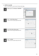
Page 49: ...e comments column and 003 is selected Input the file name into the Comments Here inputs the Product A into the comment Input the character using the keyboard of the PC 2 Input the character to be marked Press The screen is changed into Character Setting one Adjust the cursor to the first line 01 of the screen and press Re adjusting the cursor to the first line 01 and then pressing double clicking ...

Page 50: ...input the double byte character Press Here inputs ABCD Input the character using the keyboard of the PC The character ABCD is input 3 Set the marking condition Here describes the procedure for setting marking conditions using the following sample character height 4mm character width 4mm X position 20mm Y position 5mm and character interval 5mm Press SET 3 4 1 ...

Page 51: ...t 4 Input the value using the keyboard of the PC Press the setting value of the Character Width Input 4 Input the value using the keyboard of the PC Press the setting value of the X Position Input 20 Input the value using the keyboard of the PC CHARACTER 2 3 4 5 ...

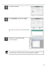
Page 52: ...alue of the Y Position Input 5 Input the value using the keyboard of the PC Press the setting value of the Character Interval Input 5 Input the value using the keyboard of the PC Press Image and check the image screen 6 7 8 ...

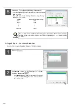
Page 53: ...r setting laser power at 30 and scan speed at 300mm s Press Press setting value of the Laser Power Input 30 Input the value using the keyboard of the PC Press setting value of the Scan Speed Input 300 Input the value using the keyboard of the PC 1 2 3 ...

Page 54: ... in OPEN state the dialog notifying that the shutter is already in OPEN state is appeared Click OK set the shutter into CLOSE and then select either procedure A or procedure B Press Series on the Start of guide indication dialog box Here the guide indication is activated in Series with the laser marker If the file No under editing on PC is also existed on the head the overwriting confirmation dial...

Page 55: ...ing continuous guide indication is closed and the End of guide indication dialog box is displayed Besides the time of guide indication is displayed Set the shutter lever to OPEN Press either Fig A or pull down File TEST Fig B If the shutter is in CLOSE state the dialog that notifies the shutter is already in CLOSE state is appeared Click OK set the shutter into OPEN and then select either procedur...

Page 56: ...nder editing on PC is also existed on the head the overwriting confirmation dialog box shown in the right figure is displayed If the same file No is not existed in the head the overwriting confirmation dialog box is not displayed After completing the marking the End of printing dialog box is displayed Besides the marking time is displayed 9 ...

Page 57: ... and pull it out The laser radiation indicator is lit off When not using the laser marker pull out the key switch and store it under the control of the laser safety manager in charge of controlling the laser marker When the laser marker is not used for a significant period of time be sure to save the back up data of the laser marker files During the unelectrified period the battery for the back up...

Page 58: ...function character of the counter The detail is described in b Input the counter function character P 60 3 Set the conditions of the function character of the counter and laser 1 Set the counter The detail is described in a Set the counter P 59 Set each condition referring to relative item shown below 3 Set the marking condition P 50 and 4 Set the laser P 53 in 2 1 3 Procedure from Laser Marker Se...

Page 59: ...P 106 for detail setting Press and press COUNTER Set 1 to Init Initial value Input the numeric using the keyboard of the PC Set 1000 to End End value Input the numeric using the keyboard of the PC Set 1 to Step Input the numeric using the keyboard of the PC 1 2 3 4 ...

Page 60: ...s Adjust the cursor to the first line 01 and press Re adjusting the cursor to the first line 01 and then pressing double clicking the same cursor performs the same operation Press COUNTER Set 4 to the Figure Set the display digit using button The display digit can be set among 1 to 8 EDIT REFERENCE 1 2 3 4 ...

Page 61: ...of the marking charac ter Press and check the image The 0000 is displayed The counter becomes 0000 because the current value of the counter is not impossible to be speci fied in remote mode In PC control mode the current value is displayed in image style FUNC INPUT SET CHECK 5 6 7 ...

Page 62: ...t the lot function character P 64 3 Set the conditions of the function character of the counter and laser 1 Set the lot The detail is described in a Set the lot P 63 Set each condition referring to relative item shown below 3 Set the marking condition P 50 and 4 Set the laser P 53 in 2 1 3 Procedure from Laser Marker Setting to Test Marking P 49 3 5 Marking Condition P 110 3 6 Laser Setting P 126 ...

Page 63: ...te to Periods Check Month to Unit Check Month for setting The unit is set to Month with Month state The lot function is available for setting up to 4 1 to 4 per file Other than Curr date it is possible to select Periods among Expiry 1 to Expiry 4 Refer to 3 4 4 Setting of Lot Function P 107 for details REFERENCE REFERENCE 1 2 3 4 ...

Page 64: ...he lot function character Refer to 3 3 3 Input of Function Character P 90 for details Press Adjust the cursor to the first line 01 of the screen and press Re adjusting the cursor to the first line 01 and then pressing double clicking the same cursor performs the same operation Set the start and end of the duration using min and max The number of division setting range and setting method are differ...

Page 65: ...Lot No Set the lot function No using button Press and then press The SFT 1 is input in the 01 line of the marking string Press and check the image The image of the target marking character is displayed FUNC INPUT SET 3 4 5 6 ...

Page 66: ... expiry date function character P 68 3 Set the conditions of the function character of the expiry date and laser 1 Set the expiry date The detail is described in a Set the expiry date P 67 Set each condition referring to relative item shown below 3 Set the marking condition P 50 and 4 Set the laser P 53 in 2 1 3 Procedure from Laser Marker Setting to Test Marking P 49 3 5 Marking Condition P 110 3...

Page 67: ...ss EXPIRY Here the condition is set to the Expiry 1 Input 30 to the numeric value column of Expi Input the character using the keyboard of the PC Check D Day to Expiry 1 Expiry Condition Check D for setting The unit is set to Day with D The expiry is available for setting up to 4 1 to 4 per file REFERENCE 1 2 3 ...

Page 68: ...Press Adjust the cursor to the first line 01 on the screen and press Re adjusting the cursor to the first line 01 and then pressing double clicking the same cursor performs the same operation Press EXPIRY Set 1 to Expiry No Set the expiry No using button Set 2 to Figure Set the display digit using button EDIT 1 2 3 4 5 ...

Page 69: ... The unit is set to Month with Month Check Zero indication Check Zero indication for setting The display state is set with Zero indication Press Continuously check Day Check Day for setting The unit is set to Day with Day FUNC INPUT 6 7 8 9 ...

Page 70: ...te is set with Zero indication Press and then press The 02 M1 02 D1 is input in the 01 line of the marking string Press and check the image The image of the target marking character is displayed FUNC INPUT SET The day after 30days from the cur rent date is displayed 10 11 12 ...

Page 71: ... the date The detail is described in a Input date function character P 72 2 Set the conditions of the function character of the date and laser Set each condition referring to relative item shown below 3 Set the marking condition P 50 and 4 Set the laser P 53 in 2 1 3 Procedure from Laser Marker Setting to Test Marking 3 5 Marking Condition P 110 3 6 Laser Setting P 126 ...

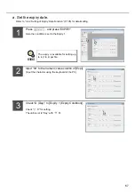
Page 72: ... the screen and press Re adjusting the cursor to the first line 01 and then pressing double clicking the same cursor performs the same operation Press CURRENT Set 2 to Figure Set the display digit using button Check Hour 24 Check Hour 24 for setting The unit is set to Hour with Hour 24 The display digit can be set among 1 to 6 EDIT REFERENCE 1 2 2 3 4 5 ...

Page 73: ...ntinuously set 2 to Figure Set the display digit using button Check Minute Check Minute for setting The unit is set to Minute with Minute Check Zero indication Check Zero indication for setting The display stateO is set with Zero indication The display digit can be set among 1 to 6 FUNC INPUT REFERENCE 6 7 8 9 10 ...

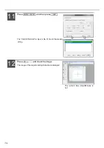
Page 74: ...d then press The 02 H0 02 m0 is input in the 01 line of the marking string Press and check the image The image of the target marking character is displayed FUNC INPUT SET The current time Hour Minute is set 11 12 ...

Page 75: ...tting 88 3 4 Function Setting 104 3 5 Marking Condition 110 3 6 Laser Setting 126 3 7 Image Display 130 3 8 Guide Indication 134 3 9 Test Marking 138 3 10 Send Read 140 3 11 PC Control Remote Mode 144 3 12 Switching Language between Japanese and English 147 3 13 Error History 148 3 14 Environmental Setting 150 ...

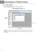
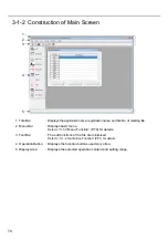
Page 76: ... This screen is called Main Screen The Language is displayed when the LP 310 setting software is installed into the PC installed Windows Japa nese OS When the LP 310 setting software is installed into the PC installed Windows English OS the Language is not displayed Operation Button Main Screen Japanese ENGLISH Switching P 147 ...

Page 77: ...acter Condition P 115 CAD Condition P 120 Laser Check P 124 Marking Condition P 110 Screen for Laser Setting P 126 Line Width P 127 Marking Pitch P 127 Adjustment of Laser Start End Points P 128 Adjustment of Marking Quality P 129 Laser Setting P 126 Image Display P 130 Test Marking P 138 Guide Indication P 134 Center Position Indication P 134 Guide Indication P 134 Cautions P 136 Test Marking P 1...

Page 78: ...enu Bar Displays basic menu Refer to 3 1 3 Menu Function P 79 for details 3 Tool Bar The edit functions of the file are minimized Refer to 3 1 4 Tool Button Function P 81 for details 4 Operation Button Displays the function buttons used very often 5 Display Area Displays the selected operation content and setting range 2 1 3 4 5 ...

Page 79: ...ocessing related to the send read of the marking file Clicking performs the same function P 140 ERROR Displays the date and content of the error occurred in the past P 148 ENVIRONMENT Sets the environment of the laser marker and PC P 150 Exit Selects this function when finishing this software Item Description Cut Cuts the selected line Copy Copies the selected line Paste Pastes the selected line j...

Page 80: ...Displays the opening windows in cascade status Tile Displays the opening windows in tile status Arrange Arranges the shifted icons at lower side Minimize Minimizes all the displaying windows Item Description Manual Displays the operation manual About Version Information Selects this item when checking the version information of this software Clicking OK button closes this window ...

Page 81: ...under editing When saving overwriting the new created registration file with its file name is not registered after editing the dialog box for setting file name is appeared Copy button Click this button for copying the selected line Cut button Clock this button for cutting the selected line Paste button Click this button for pasting the selected line just after copied Exit button Click this button ...

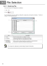
Page 82: ...Click Item Description 1 File No Total 120 marking files are available for setting 2 Comments The marking file name can be added to each file No This file name differs from the registration file name 3 FILE COPY FILE PASTE FILE DELETE All the contents of the marking file are available for copy paste delete This function is useful for setting the similar operation The image can be displayed by doub...

Page 83: ...ted by either selecting 1 or clicking 2 icon described above If the existing file is under editing without saved the check dialog box LP 310 Setting Software whether the current file requires saving or not is appeared 1 File New File 2 Click Item Description Yes Saves overwrites the registration file under editing and then creates a new registration file No Deletes all registration files under edi...

Page 84: ...Open 2 Click File name Sets the file name of the registration file to be read Files of type Enables to read either the registration file with LLM extension or backup file with LLB extension The warning might be appeared depending on the content of the read file and also might be required to read that file after correcting In this case since the content of the read file has not been changed unless ...

Page 85: ...is operation the registration file under editing is saved as the registration file with other file name user named Selecting File Save As appears the dialog box for setting file name The registration file under editing is saved by setting the file name and then clicking Save Clicking Cancel closes the dialog box and returns to the previous screen 1 File Save 2 Click icon Refer to the next procedur...

Page 86: ...dent sub file to be used for marking Registration File Marking File File No Comments 001 Mark lot No of Product A Sample 002 Mark lot No of Product B Sample 003 Mark serial No of Product C Sample 004 005 006 007 008 009 010 120 Create one registration file for each laser marker Sample of registration file name Product Line A LLM Create file per marking content work Max 120 files ...

Page 87: ...87 MEMO ...

Page 88: ...r string If this warning is appeared the paste is invalid Refer to 3 3 3 Input of Function Character 5 Input optional character string P 100 for details 1 View Character 2 Click Item Description 1 COPY Copies the selected line 2 PASTE Pastes the selected line just copied 3 INSERT Inserts one line just before selected line Note that if inserting one line just on the 30th line the character string i...

Page 89: ... characters for input Click Character Setting button Select line to be set and click button EDIT Double click line to be edited Inputting Of Characters dialog box is appeared Input the string to be marked using the keyboard The input character is appeared in the marking string field Click save the entered string and close the dialog box SET Click close the dialog box and return to the previous scr...

Page 90: ...e corresponding radio button 3 Zero indication Enables to select either item by checking the corresponding radio button The setting date is displayed as setting on PC on the image display 1 2 3 Radio Button Description A D Sets the dominical year Era year Sets the era year Month Sets the month Day Sets the day AM PM Sets either morning or afternoon Hour 24 Sets the 24 hour time Hour 12 Sets the 12...

Page 91: ...ay Content and Zero indication Click The 7 digit character string beginning with in single byte character is displayed in the marking character string field FUNC INPUT Click save the character string set and close the dialog box SET Click close the dialog box and return to the previous screen Cancel ...

Page 92: ...e functionnal character string 2 0 Sets zero indication Set the R justified single byte space 3 The display digit from 1 to 6 is displayed in the 4 Y Sets the dominical year y Sets the era year M Sets the month D Sets the day H Sets the 24 hour time h Sets the 12 hour time m Sets the minute w Sets the week 5 0 Sets the current date with zero fixed 0 1 Y 0 1 2 3 4 5 ...

Page 93: ...responding radio button The setting date is displayed on the image display as setting on PC The expiry date is referred to the date adding the expiry to the current date The expiry is available to memorize 4 patterns with the expiry No 1 to 4 Refer to Setting of Expiry Date Function P 105 for details 1 2 3 4 Radio Button Description A D Sets the dominical year Era year Sets the era year Month Sets...

Page 94: ...ure Display Content and Zero indication Click The 7 digit character string beginning with in single byte is displayed in the marking character string field FUNC INPUT Click save the character string set and close the dialog box SET Click close the dialog box and return to the previous screen Cancel ...

Page 95: ... character string 2 0 Sets zero indication Set the R justified single byte space 3 The display digit from 1 to 6 is displayed in the 4 Y Sets the dominical year y Sets the era year M Sets the month D Sets the day H Sets the timer in 24 hours h Sets the timer in 12 hours m Sets the minute w Sets the week 5 is varied in accordance with the lot function No 1 to 4 0 1 Y 1 1 2 3 4 5 ...

Page 96: ... Zero indication Marks value in right justified and mark 0 to the left R Justified Marks value in right justified and blanks left column Click COUNTER tab The Counter Input dialog box is appeared Select Figure and Zero indication Click The 7 digit character string beginning with in single byte is displayed in the marking character string field FUNC INPUT Click save the character string set and clo...

Page 97: ...lue every step Refer to 3 4 3 Setting of Counter Function P 106 for details The processing of the final value is repeated The counter ending is output at final value and the value is cleared at the next trigger and the marking is started from the initial value In case of marking from the initial value again set the current value at 0 or perform the marking after transferring In case of performing ...

Page 98: ...ets the lot No with button The setting range is selectable among 1 to 4 1 Click LOT tab The Lot Input dialog box is appeared Select Lot No Click The 7 digit character string beginning with in single byte is dis played in the marking character string field FUNC INPUT Click save the character string set and close the dialog box SET Click close the dialog box and return to the previous screen Cancel ...

Page 99: ...ndicates the function character for lot 3 is varied in accordance with the lot function No 1 to 4 The lot function is referred to the marking function that marks the character string set with a certain duration Refer to 3 4 4 Setting of Lot Function P 107 for details S F T 1 1 2 3 REFERENCE ...

Page 100: ...on for marking the optional character string in the ASCII code using the communications from the external device such as PLC 1 Char No Sets the character No with button The setting range is selectable among 1 to 4 2 Figure Sets the figure with button The setting range is selectable among 1 to 30 The optional character string character string Nos 1 to 4 can be applied to the registration file 1 to ...

Page 101: ... code using the RS 232C communication from the external device such as PLC Refer to 4 External Control P 155 for details Also the image is displayed with in the image display screen Click FREE tab The Input of optional character string dialog box is appeared Select Char No and Figure Click The 7 digit character string beginning with in single byte is dis played in the marking character string fiel...

Page 102: ...he registration character it needs to register the character beforehand Click ENTRY tab The Input of registration character dialog box is appeared Select the registration character to be input Click The 3 digit character string beginning with in single byte is dis played in the marking character string field FUNC INPUT Click save the character string set and close the dialog box SET Click close th...

Page 103: ...er Code Table P 198 for detail content of the registration character at initial condition Refer to 3 14 2 Environmental Setting Related to PC P 152 for details of the user font setting It also is possible to input function by double clicking the image of the registration character In case of not registered the registration character in the selected user font nothing is displayed To create the new ...

Page 104: ...the Function Setting screen The Function Setting dialog box is appeared by either selecting 1 method or clicking 2 button described above In this dialog box there are three tabs EXPIRY COUNTER and LOT as shown in the following figure and each function is set in this dialog box The content set in this dialog box is reflected to the character setting 1 View Set Func 2 Click ...

Page 105: ...iry Nos from 1 to 4 are available to be set 2 Expi Expiry The setting is available for the range from 1 to 999 3 Unit Selects one unit from Y Year M Month D Day h hour and m minute by checking the radio button 4 Today included Checking the Today included check box calculates the expiry including today Note that when checking the unit among D Day h hour or m minute this calculation including today ...

Page 106: ... defined by the initial and end values the counter value is not marked and the counter end signal is output If the current value is reached to the end value the external output counter end signal is output the counter end output is reset with the next trigger and the laser marker is performed marking from the initial value When the PC itself is in operation and remote mode is selected as the contr...

Page 107: ... The number of the segments setting range and setting method are varied depending on the selected Unit 5 Marking Characters Sets the character string to be marked during the setting Period 6 COPY CUT PASTE Copies cuts or pastes the selected character string 7 DEL PERI DELETE PERIOD Deletes the period and character string of the selected line 8 Lot Func COPY Copies whole lot function 9 Lot Func PAS...

Page 108: ...the input field of Marking Characters within 10 letters Input the character in double byte for Japanese OS and in single byte for English OS 2 In case of selecting Y M year month or M D month day for the period condition Sample with the period condition Y M year month Input the period into the input field within the setting range of each period condition in single byte character Input the characte...

Page 109: ...marking character string within 10 letters Input the character in double byte for Japanese OS and in single byte for English OS If the period condition is changed all the preset periods are deleted In case of setting 15 to 17 with the period condition set on Hour it means that the period is between 15 00 to 17 59 If the period is required to set from 22 o clock to 3 o clock the next day the user n...

Page 110: ...ons for marking character string and CAD file The Marking Condition dialog box is appeared by clicking either selecting 1 method or clicking 2 button described above In this dialog box there are 4 tabs GENERAL CHARACTER CAD and LASER and each condition is set in each tab 1 View Condition 2 Click ...

Page 111: ...ing or CAD file at a position symmetric to the Y axis Check box 2 Flip X axis symmetry Marks the character string or CAD file at a position symmetric to the X axis Check box 3 X Offset Moves the origin in X direction 25 00mm Step 0 01mm 4 Y Offset Moves the origin in Y direction 25 00mm Step 0 01mm 5 Rotation Offset Rotates the character around the origin with the counterclockwise direction is def...

Page 112: ...X axis symmetric All character strings and CAD files are marked at the position symmetric to X axis Both horizontal and vertical inversions are available to be set simultaneously The relation between the respective check box set ON OFF and image indication is as follows Mirror Y axis symmetric OFF Mirror Y axis symmetric ON Flip X axis symmetric OFF Flip X axis symmetric OFF Mirror Y axis symmetri...

Page 113: ...he counterclockwise direction is defined as the forward rotation direction Setting range 180 0 to 180 0 Step 0 1 The X Y offset and rotation offset can be set simultaneously The setting sample of each offset is shown as follows Rotation Offset 0 0 Rotation Offset 45 0 X Offset 0 00mm X Offset 0 00mm Y Offset 0 00mm Y Offset 0 00mm Rotation Offset 45 0 X Offset 3 00mm Y Offset 3 00mm Even if X Y of...

Page 114: ...ecting misalignment to the line axis caused when the laser marker is installed Set this function to check the actual marking results and apply fine adjustment If overall conditions are set before other conditions are set it becomes difficult to set the character conditions and CAD conditions REFERENCE CHECK ...

Page 115: ...haracter string among Straight Line Tilt Angle and Fan Line Form Select the shape using the list box 5 Font Selects the font file to be used for displaying the marking character string of each line by setting software and marking the character string by the laser marker Select the font using the list box 6 Bold Enables to set the thickness of the character stroke 0 00mm to 6 00mm Step 0 01mm 7 Las...

Page 116: ... 0 01mm 3 X Y Position Moves the marking start position of the character string in the X direction for the X position setting and in the Y direction for the Y position setting 25 00mm Step 0 01mm 4 Character Interval Sets the pitch between one character and another character 0 00 to 25 00mm Step 0 01mm 5 Line Interval Sets the interval between one line and another line 0 00 to 25 00mm Step 0 01mm ...

Page 117: ...Y direction for the Y position setting 25 00mm Step 0 01mm 4 Character Interval Sets the pitch between one character and another character 0 00 to 25 00mm Step 0 01mm 5 Line Interval Sets the interval between one line and another line 0 00 to 25 00mm Step 0 01mm 6 Tilt Angle Rotates the characters around the marking start position The counterclockwise direction is the forward direction 180 0 Step ...

Page 118: ... 01mm 6 Character Interval Angle Angle between one character and another character 180 0 Step 0 1 7 Line Interval Radius Sets the pitch between one line and another line 0 00 to 25 00mm Step 0 01mm 8 Turn Right Clockwise circle outside of fan shape Turn Left Counter clockwise circle inside of fan shape Sets the items of clockwise circle outside of fan shape and counterclockwise circle inside of fa...

Page 119: ...arking quality with the test marking and then apply to the actual marking In case of marking the bold character set the value with the ratio of the character height against the character width be one fourth to four Laser Power Revise Setting of the correction for the laser power set on the laser setting screen in the range of the setting line Setting range 0 to 200 Scan Speed Revise Setting of the...

Page 120: ... Y Appoint 5 Size Specifies the size of X Y directions of the rectangle to which a converted CAD data are circumscribed 0 03 to 50 00mm Step 0 01mm 6 Laser Power Revise Enables to set the correction for the laser power set on the laser setting screen 0 to 200 7 Scan Speed Revise Enables to set the correction for the scan speed set on the laser setting screen 50 to 200 8 Origin Specifies which part...

Page 121: ...ile is set 1 Add the CAD file The following dialog box is appeared by clicking button on the right of the list box for CAD file When selecting the location of the CAD file the DXF file can be selected The selected file is copied to the folder named Cad under the folder installed the PC setting software Refer to Character Code Table P 198 for details of the available CAD file REFERENCE Add CAD file...

Page 122: ...hich a converted CAD data are circumscribed If Y Appoint or X Y Same is set in the size specification field this item is invalid Setting range 0 03 to 50 00mm Length in Y axis direction Specify the size of the vertical direction of the rectangle to which a converted CAD data are circumscribed If X Appoint or X Y Same is set in the size specification field this item is invalid Setting range 0 03 to...

Page 123: ... cannot be marked as displayed in the image display if a DXF file created by AutoCAD is read in by the setting software Refer to Readable DXF File P 207 for details of the correspondence table between the LP 310 setting software and the drawing function of AutoCad Laser Power Revise Adds the correction to the laser power of the setting line Setting Range 0 to 200 Scan Speed Revise Adds the correct...

Page 124: ...on Setting and Image Display be opened these windows are closed forcibly However since the data is remained open these windows again after the laser check is OFF 3 When marking with the laser check perform TRIG IN or test marking after transferring the file just the same as the marking characters and CAD file 4 The laser power for the laser check is reflected by the power set at Laser Setting When...

Page 125: ...125 MEMO ...

Page 126: ...m 3 Line Width Sets the with of the stroke of the marked character 0 01 to 2 00mm Step 0 01mm 4 Start Wait Adjusts the timing for turning ON the laser at the start point 50 to 150 Step 1 5 End Wait Adjusts the timing for turning OFF the laser at the ending point 50 to 150 Step 1 6 Marking Pitch Sets the density for marking a bold character 0 00 to 2 00mm Step 0 01mm 7 Marking Quality Sets the numb...

Page 127: ...0 01 to 2 00mm Initial Value 0 20mm 3 6 3 Marking Pitch This item sets the density of the marking of the bold character Marking bold characters Even if the setting for the line width is adjusted the width of the character stroke being marked is not changed The setting value of the line width is differed from the width of the actual marked strokes depending on the material of the work being marked ...

Page 128: ...t Adjusts the timing for turning on the laser at the start point The smaller the value is the darker deeper the marked character at the start point is Dark deep Proper Light shallow 50 150 Setting Range 50 to 150 Initial Value 100 Laser end point adjustment Adjusts the timing for turning off the laser at the end point The larger the value is the darker deeper the marked character at the end point ...

Page 129: ...on can be set in eleven steps When a small character is marked the character looks a curve even if this parameter is set relatively rough When a large character is marked the character looks a distorted curve unless this param eter is set fine The larger the value of the marking quality is the longer the marking time becomes REFERENCE CHECK ...

Page 130: ...zoom in Magnifies the scope specified with the selection window to the maxi mum size of image display 4 Adjust the marking position Moves the character string by dragging the image 5 Adjust the display position Adjusts the display position by dragging the edit area to a new position 6 Magnification list box Selects the desired magnification using the list box Selectable magnification 100 to 100000...

Page 131: ...ation function When clicking button the mouse cursor is changed into icon With this state click the left mouse button to specify the scope using the selection window portion enclosed with dotted lines Then the selected scope is magnified to the full size of the image display dialog box by releasing the button The reference position of the zoom in out is set on the center of the image display scree...

Page 132: ... Shift Arrow key The character string is moved per 0 1mm When clicking the right mouse button on the selected character string the character setting screen and marking condition screen can be opened If the marking position is moved and the character string is moved out of the scope of the marking area Marking data has exceeded marking area is displayed Shift the character string into the scope of ...

Page 133: ...icking button the mouse cursor is changed With this state press and hold the left mouse button on the image display and drag the image with the mouse to the desired position for display and release the mouse The display position of the image is moved ...

Page 134: ...escribed above When the shutter is set to CLOSE the dialog box indicating Start of guide indication is appeared When activating the guide indication perform the guide indication with the shutter guide indication switching lever closed Since the power of the guide laser is 1mW or less red work is not processed in almost all cases However the color change may be caused on an object sensitive to red ...

Page 135: ...en finishing the guide indication the dialog box indicating During guide indication is closed and then the dialog box indicating the finish of the guide indication End of guide indication is appeared Besides the guide indication time is also appeared No Item Description a Indicates the frequency of the guide indication b Average time of guide indication Indicates the average time of the guide indi...

Page 136: ...uide indication is closed and then the dialog box indicating the finish of the guide indication End of guide indication is appeared Besides the guide display time is also appeared 3 Cancel By clicking this button the guide indication is canceled 3 8 3 Cautions It is impossible to perform the guide indication for an empty file including no setting Click OK button re select the file and select the o...

Page 137: ...137 MEMO ...

Page 138: ...raed When selecting Yes in the dialog box Start of printing the file is transferred and the test marking is started After ending the test marking the End of printing dialog box is appeared Besides the marking time is also displayed When performing the test marking set the shutter guide indication switching lever to OPEN For some PC models the dialog box below may be hidden behind the main screen o...

Page 139: ...tched to PC control mode during the marking the mode is switched after completing the marking The test marking time displayed in the test marking may be slightly differed from the actual marking time In case of requiring the precise marking time perform the marking using the external control refer to Chapter 4 and measure the time using the marking start trigger signal and marking ending signal Wh...

Page 140: ...red In this dialog box only the files that have already been set are displayed They are displayed with their file Nos 3 digits and comments 1 File SEND READ 2 Click In case of marking in remote mode it needs to transfer marking file to the head beforehand Item Description 1 Checked File Only Selects the marking file that is desired transferring from the files already set and transfer only the chec...

Page 141: ... marking file is large it may be that all files cannot be transferred When trying to transfer the marking file with large data size the warning message is displayed Item Description 1 Yes Overwrite the file 2 No Not overwrite the file 3 No to All Not overwrite all files 4 Yes to All Overwrite all files If the marking file cannot be transferred reduce the file capacity by deleting the unnecessary m...

Page 142: ...d at a time When the laser marker is not used for a significant period of time be sure to save the back up data of the laser marker files During the unelectrified period the battery for the back up will be out of charge and the data in the laser marker may be deleted Though the LLB file can be opened with the setting software of PC it cannot be overwritten and registered The LLB file can be stored...

Page 143: ...143 3 10 4 Restore The LLB file will be written back to the laser marker Since all the marking files in the laser marker are deleted by performing RESTORE perform the backup as required CHECK ...

Page 144: ...is started up with connecting the PC it can be changed into the remote mode by the LP 310 setting software By clicking either 1 or 2 the dialog box for confirming whether to set the laser marker into remote mode or not is appeared When selecting Yes Remote button is changed to PC Control button This product has two types of the control mode PC control mode and remote external control When turning ...

Page 145: ...145 When returning the mode of the laser marker to the PC control mode click button When performing the marking in remote mode external control refer to 4 External Control P 155 for details REFERENCE ...

Page 146: ... can be changed into PC control mode by the LP 310 setting software By clicking either 1 or 2 the dialog box for confirming whether to set the laser marker into PC control mode or not is appeared When selecting Yes PC Control button is changed to Remote button When returning the mode of the laser marker to the PC control mode click Remote button This product has two types of the control mode PC co...

Page 147: ...this LP 310 setting software is installed into Japanese OS The Japanese English display switching function is the display switching of the LP 310 setting software The language can be switched between Japanese and English for Japanese Windows However this function is not available for English Windows The errors related to Windows are displayed in Japanese available only for Japanese OS CHECK CHECK ...

Page 148: ...the Error History dialog box Details of Error History Code Released interlock of the power supply box E01 Entered the laser radiation stop of the I O connector E02 No marking file is existed E04 Released the interlock during marking E10 Entered laser radiation stop during marking E11 Occurred shutter operation during marking E12 Opened head cover E20 Occurred error on the galvanometer E21 22 Occur...

Page 149: ...149 MEMO ...

Page 150: ...a year and change the value using the keyboard The settable era year is from 1 to 99 It is changeable using up down button Adjust the clock setting of the laser marker to that of the PC The date and time set on the PC are applied only when displaying the image of the current date and time etc The date and time set on the PC are also applied to display the current date and so on as an image and per...

Page 151: ... one second 1200 2400 4800 9600 19200 38400 Select in the list box Parity Specifies an error detection bit to each information delimited by a stop bit NA Odd Even Select in the list box Stop bit Specifies the length of the delimiter signal of the information sent received 1 bit 2 bit Select in the list box Checksum Specifies an error detection code to each information delimited by a delimiter NA A...

Page 152: ... s PC By inputting the screen size unit inch the image display edit area is set to almost the same size of the marking area of the laser marker when the magnification is set as 100 Click SET Reflects the setting contents Click CANCEL The change is ignored and the settings are returned to the original condition and then the dialog box is closed Refer to 3 7 Image Display P 130 for details of the im...

Page 153: ... system font System Font Font to be selected when setting the character condition and CAD condition Refer to Character Code Table P 198 for details of the type of the system fonts 1 Add button Adds the font file to the list of the system font Since the following dialog box is appeared select the desired font file to be added 2 Delete button Deletes the font file registered in the list of the syste...

Page 154: ... list by one The order displayed in the list is the order displayed when the font is set in the character condition and CAD condition 3 User Font Font files including the JIS level 1 Kanji and registration character except for symbols and alphanumeric characters Refer to Character Code Table P 198 for details of the character type of the user fonts Refer to 3 3 3 Input of Function Character 6 Inpu...

Page 155: ...155 4 External Control 4 1 Control Through I O Connector 156 4 2 Control with RS 232C 166 ...

Page 156: ...tch of the laser marker the product becomes remote mode external control mode When performing the guide display and test marking from the PC release the remote mode following the indication displayed on the PC screen and set the mode of the laser marker into PC control mode 1 Turn ON the power supply of the laser marker 2 Control the laser marker from the external Turn the key switch of the power ...

Page 157: ...al power supply When performing marking connect the I O connector No 1 and No 3 When setting the state between No 1 and No 3 into OPEN the emergency stop is activated and the marking becomes invalid Be sure to connect the interlock terminals on the connecting point 24V 500mA When performing marking connect the I O connectors No 4 and No 15 When setting the state between No 4 and No 15 into OPEN th...

Page 158: ... performing marking connect the I O connectors No 4 and No 15 When setting the state between No 4 and No 15 into OPEN the laser radiation is activated and the marking becomes invalid When performing marking connect the I O connectors No 1 and No 3 When setting the state between No 1 and No 3 into OPEN the emergency stop is activated and the marking becomes invalid 㻝㻤 㻝㻥 䠑 䠒 䠓 䠔 㻞㻜 㻝㻠 㻝㻡 㻝㻢 䠏 3 TRI...

Page 159: ...d for switching the file No 1 to No 120 saved in the head Keep the input status of D0 to D6 while using the selected file 18 D1 6 D2 19 D3 7 D4 20 D5 8 D6 15 OUT COM Output common Common for output 16 READY Marking ready output When the marking is ready for starting in TRIG IN input receivable state the output becomes ON 25 COUNTER END Counter reset output When the counter reaches to the ending va...

Page 160: ...d Equivalent to PNP open collector output Input common 14 external power supply Output common 15 external power supply GND Input common 14 external power supply GND Output common 15 external power supply The input and output circuits of this product are compatible with both NPN PNP open collector output However mixing NPN and PNP is not allowed If the open collector to be connected is NPN use NPN ...

Page 161: ...en collector output Input common 14 external power supply Output common 15 external power supply GND Input common 14 external power supply GND Output common 15 external power supply The input and output circuits of this product are compatible with both NPN PNP open collector output However mixing NPN and PNP is not allowed If the open collector to be connected is NPN use NPN to all the input and o...

Page 162: ... OPEN the laser radiation is stopped When setting this state into OPEN during marking the laser pumping is stopped When setting this state into OPEN during non marking the marking ready output becomes OFF Terminal No 17 Counter Reset Input COUNTER RESET This terminal sets the input to ON when resetting the counter Input COUNTER RESET with holding the input status of the file selection D0 to D6 Whe...

Page 163: ...nput is entered Terminal No 13 Alarm Output ALARM When an alarm is occurred the output becomes OFF The laser radiation stops when this alarm output becomes ON The content of the alarm is displayed with error code in the head display panel I O Connector Power Supply Terminal No 1 Power Supply for External Device 12V 12V This is the power supply for external device The max output current is 100mA Te...

Page 164: ...e for 10ms or more T5 within 5ms Time from inputting the trigger to the start of the actual marking Key Switch Head display panel Radiation Display READY Output File Selection Input TRIG Input Laser Radiation Stop Input Alarm Output Manual Shutter OFF ON OFF ON OFF ON OFF ON OFF ON OFF ON CLOSE OPEN OFF ON OFF ON 888 Rotation Display T1 T2 T4 T4 T3 T3 T5 T5 File No Display Error No Display 1 File ...

Page 165: ...ding the input status of the file selection D0 to D6 When the file No changing command FNO is set by RS 232C input of D0 to D6 is not required READY Output TRIG Input Counter Reset Input Counter End Input OFF ON OFF ON OFF ON OFF ON Counter End Value Counter End value 1 Counter Value 1 Counter Value 2 Counter Value 3 Counter Value 1 CHECK ...

Page 166: ...ease the remote mode following the indication displayed on the PC screen and set the mode of the laser marker into PC control mode 1 Accommodate the setting of the laser marker and that of the communication condition of the connected external device 2 Turn ON the power supply of the external device Refer to 4 2 4 Setting of Communication Condition P 168 for details 4 Control the laser marker by ex...

Page 167: ...it 2 bits Data Bits 8 bits fixed Baud Rate 1200 2400 4800 9600 19200 38400 Parity None even odd Check Sum NA available Delimiter CR LF CR Flow Control None three wire method Reception Timer Reception timeout monitoring available 10 seconds for reception Refer to 3 14 1 Environmental Setting Related to Laser Marker P 150 for details of the setting of the communication condition No Signal Name Funct...

Page 168: ...ited by a stop bit NA Odd Even Select in the list box Stop Bits Specifies the length of the delimiter signal of the information sent received 1 bit 2 bit Select in the list box Check Sum Specifies an error detection code to each information delimited by a delimiter NA Available Select in the list box Delimiter Specifies a symbol of rough separation on the information sent received CR CR LF Select ...

Page 169: ... the key switch of the power supply BOX clockwise The laser marker starts up in the remote mode Open the manual shutter 4 Transfer File No Change Code FNO command Start Code Fixed STX 5 Check the response from the laser marker If the connection is performed properly the laser marker sends back the response data of either ACK or NAK Command Code File No Change FNO Subcommand Data Setting or Operati...

Page 170: ...ile No change FNO command Turn the key switch to ON 2 Arbitrary character string STR command 3 Status request STS command Marking ready status is 1 Marking Ready Status NO YES 4 Marking Trigger MRK command Change marking contents Re send STS command after leaving for a while Change setting contents Turn the key switch to OFF When ending marking ...

Page 171: ...ter string STR command 3 Status request STS command Marking ready status is 1 Marking Ready Status NO YES 4 Marking Trigger MRK command Change marking contents Re send STS command after leaving for a while Change character Turn the key switch to OFF When ending marking Mark the same character 1 File No change FNO command ...

Page 172: ...1 File No change FNO command 2 Status request STS command NO YES 3 Marking Trigger MRK command Change file No Turn the key switch to OFF Mark the same character Marking ready status is 1 Marking Ready Status Re send STS command after leaving for a while Change file No When ending marking ...

Page 173: ...Reading of setting data Read Note There are some commands that disables to be specified with either S or Rʼ Data Data to be specified for each command The content of the specification is differed depending on the command 4 2 10 Communication Command and Function P 180 Check Sum Data that the lowest 1 byte is expressed with 2 characters of ASCII code by adding the codes from start code until data i...

Page 174: ...s response data is sent back Normal Reception Response Data Format Description of Each Code Name Description Start Code Fixed with ACK code 06 HEX This is the code for identifying the head of the data and recognizing the data is normal receiving response data Response Code Sends back 2 characters 00 for ACK Check Sum Data that the lowest 1 byte is expressed with 2 characters of ASCII code by addin...

Page 175: ...ength of the receiving data 07 System reserved 08 Improper subcommand 09 Improper receiving data 10 Occurred alarm 11 No specified file is existed 99 Others Check Sum Data that the lowest 1 byte is expressed with 2 characters of ASCII code by adding the codes from start code until data in binary E g Response Code 20 15 HEX 32 HEX 30 HEX 77 HEX When converting 77 HEX into 2 characters it becomes 37...

Page 176: ...a that the lowest 1 byte is expressed with 2 characters of ASCII code by adding the codes from start code until data in binary E g Command ABC Subcommand A Data 000 02 HEX 41 HEX 42 HEX 43 HEX 41 HEX 30 HEX 30 HEX 30 HEX 199 HEX When converting the lowest 1 byte AB HEX of the 199 HEX into 2 characters it becomes 39 HEX 39 HEX The valid invalid of the checksum is available to be set in the environm...

Page 177: ...r marker performs the reception timeout check monitoring the time for completely receiving data ranging from the top to the bottom of the command while a command is received when receiving the com mand sent from the external device The time of the reception timeout is 10 seconds If the command is not received completely from the top to the bottom of the data within this time it is judged that some...

Page 178: ... is set by the marking state transmission permission command Communication sequence when transmission permission is set by the marking state transmission permission command Marking Status Transmission Permission Prohibition Normal Reception Response Marking Trigger Normal Reception Response The occurrence of a warning during marking operation and the end timing of the marking are not clear Under m...

Page 179: ...marking state is returned when a marking operation is finished or an error is occurred Using Communication Control and I O Connector 25 pin Connec tor Together When the file number change command FNO is not accepted the control using I O connector is available Only the following items marking trigger MRK status request STS optional character string STR and marking status transmission permission MS...

Page 180: ...eturned Name Code Function Outline Page 1 File number change FNO Switches the file number to the specified file number P 180 2 Arbitrary character string STR Sets the arbitrary character string in ASCII code P 182 3 Counter current value CNT Sets the current value of the counter P 183 4 Counter reset CTR Resets the counter P 183 5 Status request STS Calls out the operation status of the laser mark...

Page 181: ...umber change indicates the file number to be used and the file number readout indicates the currently using file number 001 to 120 If the specified file does not exist the abnormal reception response telegram NAK11 is returned If perform of marking trigger is sent in this state the contents of the previous file number are marked STX FNO A File number 3 Bytes Check sum Delimiter CHECK ...

Page 182: ...er string with specified line number is readout in the following format Description Name Data length Outline Content Character string No 1 Indicates the character string number to be set in the file Character string No 1 to 4 Marking character string Max 30 Indicates the arbitrary character string to be marked The character string is set using ASCII code Refer to ASCII Code P 198 for details of AS...

Page 183: ...of the abnormal reception response data Readout response data Description of data 4 Counter reset code CTR 1 Counter reset This command sets the counter of the file selected by the file number change command FNO to the initial value As for the response data either normal reception response data or abnormal reception response data is returned Refer to Response Data P 174 for details of both normal ...

Page 184: ...recep tion response data Name Data length Outline Content Ready 1 Indicates the marking ready status 0 Marking busy 1 Marking ready Shutter 1 Indicates the shutter lever status 0 Shutter closed 1 Shutter opened Interlock connector 1 Indicates the interlock connector status 0 Interlock occurred 1 No interlock occurred Laser radiation stop 1 Indicates the laser radiation stop input of the I O connec...

Page 185: ...us transmission permission If the marking trigger signal from the external I O and the marking trigger command through the communication control are accepted after the marking status transmission permission is set the status is set after the marking operation is finished Readout data Description of data Error code during marking operation Name Data length Outline Content Transmission permission pr...

Page 186: ...186 MEMO ...

Page 187: ...187 5 Troubleshooting 5 1 Troubleshooting 188 5 2 Measures for Indicated Error 189 ...

Page 188: ...annot be marked The marking start command is not input Input the marking start command The distance to the work has not been calibrated Calibrate the distance to the work 54 Laser power and scan speed are not appropriate to the marking target object Raise the laser power or lower the scan speed Or perform both of them 126 The trigger signal is kept ON Since the trigger signal sensitive to the edge...

Page 189: ...nector and then turn on the key switch again 13 E12 Shutter operation during marking The shutter operation is occurred during marking Turn on the key switch again 35 E20 Cover OPEN The cover of the head is opened Contact our sales office E21 E22 X Y galvanometer error An error is detected on the galvanometer Contact our sales office The data is located out of the marking area Confirm the position ...

Page 190: ... OFF ON E04 No marking file ON OFF E10 Remote interlock connector OPEN during marking OFF OFF E11 Laser radiation stop input during marking OFF OFF E12 Shutter operation during marking OFF OFF E20 Cover OPEN OFF OFF E21 X Y galvanometer error OFF OFF E22 E23 Laser tube error OFF OFF E25 Marking file error OFF OFF E26 Area over OFF OFF E30 Backup battery voltage lowered OFF OFF E31 to E39 System er...

Page 191: ...191 6 Maintenance 6 1 Maintenance 192 ...

Page 192: ...nal For procurement of the air filter contact to our sales office Prior to this work be sure to turn off the system power Do not wipe the fθ lens strongly or with a sharp pointed object Otherwise it may cause a deterioration in the marking performance This product contains ZnSe zinc selenide in the lens mounted on the laser radiation window If the lens is damaged care should be taken of the follow...

Page 193: ...193 7 Specification 7 1 Specification 194 7 2 Outer Dimensional Drawing 195 ...

Page 194: ...an be set Marking interval interval between characters line pitch 0mm to 25mm 0 01 mm interval can be set Fan like 180 0 1 interval can be set Character array Straight line Tilt Angle Fan like Form Scan speed Max 2000mm s Numbers of Registered Files Max 120 files 3 Function Current date time marking Expiry date time marking Counter marking Lot marking RS 232C control Capital CAD marking registered...

Page 195: ...51 14 175 710 3 100 145 36 78 180 16 200 125 180 File No Error Code Indicator Laser Radiation Indicator Shutter Lever Guide Indication Switch Lever Center of Marking Marking Range 50X50 Power Supply Connector I O Connector USB Connector RS 232C Connector Handle 6 M6X1 depth 10 ...

Page 196: ...r Cooling Fan Interlock Connector FG Inlet Power Supply Connector FUSE 4 M4X0 7 depth 10 4 M4X0 7 depth 10 CO Laser Marker series POWER LP 300 2 12 5 140 57 5 255 200 70 12 5 35 30 315 210 14 5 95 Key Switch Main Power Indicator Cooling Fan Interlock Connector FG Inlet Power Supply Connector FUSE 4 M4X0 7 depth 10 4 M4X0 7 depth 10 ...

Page 197: ...197 Appendix Character Code Table 198 Readable DXF File 207 Glossary 209 ...

Page 198: ...duct When using the external device set by 2byte NUL00 HEX can be used Please add NUL00 HEX before the start code or after delimiter end code This ASCII Code differs from the ANSI Standard ASCII Code in the symbols denoted by the following codes 5C HEX 60 HEX 7E HEX Top Bottom 00 10 20 30 40 50 60 70 0 NUL SP 0 P p 1 1 A Q a q 2 STX 2 B R b r 3 3 C S c s 4 4 D T d t 5 NAK 5 E U e u 6 ACK 6 F V f v...

Page 199: ... version are represented with the outline characters on a colored background Shift JIS JIS 0 1 2 3 4 5 6 7 8 9 A B C D E F Symbols 813F 2120 814F 2130 ヽ ヾ ゝ ゞ 仝 々 〆 〇 ー 815F 2140 816F 2150 8180 2160 8190 2170 819E 2220 81AE 2230 81BE 2240 81CE 2250 81DE 2260 81FE 2270 Å Alpha numeric 824F 2330 0 1 2 3 4 5 6 7 8 9 825F 2340 A B C D E F G H I J K L M N O 826F 2350 P Q R S T U V W X Y Z 8280 2360 a b...

Page 200: ... Λ Μ Ν Ξ Ο 83AE 2630 Π Ρ Σ Τ Υ Φ Χ Ψ Ω 83BE 2640 α β γ δ ε ζ η θ ι κ λ μ ν ξ ο 83CE 2650 π ρ σ τ υ φ χ ψ ω Russian character 843F 2720 А Б В Г Д Е Ё Ж З И Й К Л М Н 844F 2730 О П Р С Т У Ф Х Ц Ч Ш Щ Ъ Ы Ь Э 845F 2740 Ю Я 846F 2750 а б в г д е ё ж з и й к л м н 8480 2760 о п р с т у ф х ц ч ш щ ъ ы ь э 8490 2770 ю я あ 889E 3020 亜 唖 娃 阿 哀 愛 挨 姶 逢 葵 茜 穐 悪 握 渥 88AE 3030 旭 葦 芦 鯵 梓 圧 斡 扱 宛 姐 虻 飴 絢 綾 鮎 或...

Page 201: ... 関 陥 韓 館 舘 丸 含 岸 8ADE 3460 巌 玩 癌 眼 岩 翫 贋 雁 頑 顔 願 き 企 伎 危 喜 器 8AEE 3470 基 奇 嬉 寄 岐 希 幾 忌 揮 机 旗 既 期 棋 棄 8B3F 3520 機 帰 毅 気 汽 畿 祈 季 稀 紀 徽 規 記 貴 起 8B4F 3530 軌 輝 飢 騎 鬼 亀 偽 儀 妓 宜 戯 技 擬 欺 犠 疑 8B5F 3540 祇 義 蟻 誼 議 掬 菊 鞠 吉 吃 喫 桔 橘 詰 砧 杵 8B6F 3550 黍 却 客 脚 虐 逆 丘 久 仇 休 及 吸 宮 弓 急 救 8B80 3560 朽 求 汲 泣 灸 球 究 窮 笈 級 糾 給 旧 牛 去 居 8B90 3570 巨 拒 拠 挙 渠 虚 許 距 鋸 漁 禦 魚 亨 享 京 8B9E 3620 供 侠 僑 兇 競 共 凶 協 匡 卿 叫 喬 境 峡 強 8BAE 3630 彊...

Page 202: ...CE 3A50 歳 済 災 采 犀 砕 砦 祭 斎 細 菜 裁 載 際 剤 在 8DDE 3A60 材 罪 財 冴 坂 阪 堺 榊 肴 咲 崎 埼 碕 鷺 作 削 8DEE 3A70 咋 搾 昨 朔 柵 窄 策 索 錯 桜 鮭 笹 匙 冊 刷 8E3F 3B20 察 拶 撮 擦 札 殺 薩 雑 皐 鯖 捌 錆 鮫 皿 晒 8E4F 3B30 三 傘 参 山 惨 撒 散 桟 燦 珊 産 算 纂 蚕 讃 賛 8E5F 3B40 酸 餐 斬 暫 残 し 仕 仔 伺 使 刺 司 史 嗣 四 士 始 8E6F 3B50 姉 姿 子 屍 市 師 志 思 指 支 孜 斯 施 旨 枝 止 8E80 3B60 死 氏 獅 祉 私 糸 紙 紫 肢 脂 至 視 詞 詩 試 誌 8E90 3B70 諮 資 賜 雌 飼 歯 事 似 侍 児 字 寺 慈 持 時 8E9E 3C20 次 滋 治 爾 璽 痔 磁 示 而 ...

Page 203: ... 90BE 4040 誓 請 逝 醒 青 静 斉 税 脆 隻 席 惜 戚 斥 昔 析 90CE 4050 石 積 籍 績 脊 責 赤 跡 蹟 碩 切 拙 接 摂 折 設 90DE 4060 窃 節 説 雪 絶 舌 蝉 仙 先 千 占 宣 専 尖 川 戦 90EE 4070 扇 撰 栓 栴 泉 浅 洗 染 潜 煎 煽 旋 穿 箭 線 913F 4120 繊 羨 腺 舛 船 薦 詮 賎 践 選 遷 銭 銑 閃 鮮 914F 4130 前 善 漸 然 全 禅 繕 膳 糎 そ 噌 塑 岨 措 曾 曽 楚 915F 4140 狙 疏 疎 礎 祖 租 粗 素 組 蘇 訴 阻 遡 鼠 僧 創 916F 4150 双 叢 倉 喪 壮 奏 爽 宋 層 匝 惣 想 捜 掃 挿 掻 9180 4160 操 早 曹 巣 槍 槽 漕 燥 争 痩 相 窓 糟 総 綜 聡 9190 4170 草 荘 葬 蒼 藻 装 走...

Page 204: ... 4560 凍 刀 唐 塔 塘 套 宕 島 嶋 悼 投 搭 東 桃 梼 棟 9390 4570 盗 淘 湯 涛 灯 燈 当 痘 祷 等 答 筒 糖 統 到 939E 4620 董 蕩 藤 討 謄 豆 踏 逃 透 鐙 陶 頭 騰 闘 働 93AE 4630 動 同 堂 導 憧 撞 洞 瞳 童 胴 萄 道 銅 峠 鴇 匿 93BE 4640 得 徳 涜 特 督 禿 篤 毒 独 読 栃 橡 凸 突 椴 届 93CE 4650 鳶 苫 寅 酉 瀞 噸 屯 惇 敦 沌 豚 遁 頓 呑 曇 鈍 な 93DE 4660 奈 那 内 乍 凪 薙 謎 灘 捺 鍋 楢 馴 縄 畷 南 楠 93EE 4670 軟 難 汝 に 二 尼 弐 迩 匂 賑 肉 虹 廿 日 乳 入 943F 4720 如 尿 韮 任 妊 忍 認 ぬ 濡 ね 禰 祢 寧 葱 猫 熱 年 944F 4730 念 捻 撚 燃 粘 の 乃 廼 ...

Page 205: ... 返 遍 便 勉 娩 弁 鞭 ほ 保 舗 鋪 95DE 4A60 圃 捕 歩 甫 補 輔 穂 募 墓 慕 戊 暮 母 簿 菩 倣 95EE 4A70 俸 包 呆 報 奉 宝 峰 峯 崩 庖 抱 捧 放 方 朋 963F 4B20 法 泡 烹 砲 縫 胞 芳 萌 蓬 蜂 褒 訪 豊 邦 鋒 964F 4B30 飽 鳳 鵬 乏 亡 傍 剖 坊 妨 帽 忘 忙 房 暴 望 某 965F 4B40 棒 冒 紡 肪 膨 謀 貌 貿 鉾 防 吠 頬 北 僕 卜 墨 966F 4B50 撲 朴 牧 睦 穆 釦 勃 没 殆 堀 幌 奔 本 翻 凡 盆 ま 9680 4B60 摩 磨 魔 麻 埋 妹 昧 枚 毎 哩 槙 幕 膜 枕 鮪 柾 9690 4B7O 鱒 桝 亦 俣 又 抹 末 沫 迄 侭 繭 麿 万 慢 満 969E 4C20 漫 蔓 み 味 未 魅 巳 箕 岬 密 蜜 湊 蓑 稔 脈 妙 96A...

Page 206: ... 輪 隣 鱗 麟 る 瑠 塁 涙 累 97DE 4E60 類 れ 令 伶 例 冷 励 嶺 怜 玲 礼 苓 鈴 隷 零 霊 麗 97EE 4E70 齢 暦 歴 列 劣 烈 裂 廉 恋 憐 漣 煉 簾 練 聯 983F 4F20 蓮 連 錬 ろ 呂 魯 櫓 炉 賂 路 露 労 婁 廊 弄 朗 984F 4F30 楼 榔 浪 漏 牢 狼 篭 老 聾 蝋 郎 六 麓 禄 肋 録 985F 4F40 論 わ 倭 和 話 歪 賄 脇 惑 枠 鷲 亙 亘 鰐 詫 藁 蕨 986F 4F50 椀 湾 碗 腕 User registered character F13F 8120 To create the new font as a user registered character contact our sales office In the initial status the registrati...

Page 207: ...ponding marking object using laser marker are listed in the following table For reading DXF file with LP 310 setting software using the CAD software review the graphic type function referring to the following table DXF Version No DXF Element Correspond able Remarks Entity Name Graphic Name R12 1 3DFACE 3D face N 2 3DLINE 3D line N 3 ARC Arc Y Converted into segment and out put 4 ATTDEF Attribute d...

Page 208: ...nd out put 30 OLEFRAME OLE frame N 31 OLE2FRAME OLE2 frame N 32 RAY Radiation half line Y Output with segment 33 REGION Region N 34 SPLINE Free curve Y Converted into segment and out put 35 TOLERANCE Geometric tolerance N 36 XLINE Line straight line Y Output with segment R14 Used Express Tools 37 ARCALIGNEDTEX T Character string on arc N 38 RTEXT Reference charac ter string N 39 WIPEOUT Masking gr...

Page 209: ...files to be marked in relation to the size and position are set Laser Setting The output and speed of the laser for marking are set Image Display The character string and size and position of the CAD file cab be confirmed before marking Guide Indication The actual character string and condition are tranced by the guide laser before marking This function is available for rough alignment etc Guide i...

Page 210: ...is scan speed revise with the scan speed revise together the data may be marked finely on the whole Mirror Inversion The set data is automatically converted into a position symmetrical with respect to the X or Y axis There are two types for the mirror inversion vertical mirror inversion and horizontal mirror inversion Offset Offset The whole setting screen of each file can be shifted in the X Y an...

Page 211: ...heck For the laser check laser beam is continuously emitted to a desired spot in the marking area Work Distance This is the reference distance from the bottom reference plane of the laser marker to the minimum spot of the marking laser This distance depends on individual product and there is a variation of around 2 0mm Marking Range This is the max range the laser marker can perform the marking Mi...

Page 212: ...212 Index Index 213 ...

Page 213: ...lock System 14 Contamination of f theta Lens 192 Control Through I O Connector 156 Control with RS 232C 166 Counter current value code CNT 183 Counter Ending Output 163 Counter reset code CTR 183 Counter Reset Input 162 D Delimiter 180 Description of Main Screen 76 Details of Commands 180 E Edit 79 Environmental humidity 194 Environmental Setting 150 Environmental Setting Related to Laser Marker 1...

Page 214: ... control mode 54 Power Connector 34 35 Power Supply BOX 12 Power Supply Display 12 Power Supply for External Device 12V 12V 163 Preface 2 Preparation 31 Preparation of Laser Marker Operation 47 Procedure from Laser Marker Setting to Test Marking 49 Protective clothing 9 Protective enclosure 8 R Radiation direction of laser beam 9 Radiation Nozzle of Laser and Guide Laser 34 Readable DXF File 207 R...

Page 215: ...No 9000 0062 20V ...

Page 216: ...Head Office 2431 1 Ushiyama cho Kasugai shi Aichi 486 0901 Japan Telephone 81 568 33 7861 Facsimile 81 568 33 8591 panasonic net id pidsx global Panasonic Industrial Devices SUNX Co Ltd 2003 2018 May 2018 9000 0062 20V About our sales network please visit our website ...

Reviews: