120
3-5-4 CAD Condition
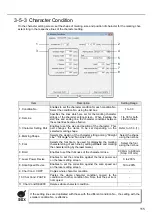
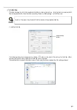
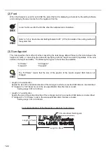
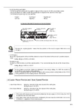
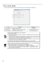
On the CAD condition screen, the conditions for setting the marking of the data created by AutoCAD and so
on (DXF file) are set.
Item
Description
Setting Range
1. CAD No.
Selects the registration No. of the CAD data to be marked
using the list box.
1 to 15
2. CAD File
Selects CAD file to be marked.
Select file using
the list box.
3. Font
Selects the font to be used for displaying the character by
the setting software and for marking by the laser marker in
case that the character is used for each CAD file.
Select font using
the list box.
4. Size Appoint
Specifies the method of either converting read image data
with leaving the ratio between the height and width, or con-
verting the data with specifying both the height and width
(regardless of the ratio between the height and width).
•
X/Y-Same
•
X/Y-Appoint
•
X-Appoint
•
Y-Appoint
5. Size
Specifies the size of X/Y directions of the rectangle to
which a converted CAD data are circumscribed.
0.03 to 50.00mm
(Step: 0.01mm)
6. Laser Power Revise
Enables to set the correction for the laser power set on the
laser setting screen.
0 to 200%
7. Scan Speed Revise
Enables to set the correction for the scan speed set on the
laser setting screen.
50 to 200%
8. Origin
Specifies which part of the graphic is aligned to the origin
(0, 0) of the coordinate system.
Select 6 locations
on a graphic.
9. X/Y Position
Moves the origin of the CAD file data in the X direction for the
X position and in the Y direction for the Y position respectively.
+/-25.00mm
(Step: 0.01mm)
10. Rotation Angle
Rotates CAD file data around the position of the origin. The
counterclockwise direction is the forward direction.
+/-180.0
°
(Step: 0.1
°
)
11. CAD Cond. COPY
Copies the whole CAD condition.
-
12. CAD Cond. PASTE
Pastes the whole CAD condition copied to the condition with
other CAD No.
-
13. CAD Cond. DELETE
Deletes whole CAD condition.
-
1
2
4
6
7
8
9
10
3
5
11
12
13
Summary of Contents for LP-310
Page 5: ...5 MEMO ...
Page 21: ...21 MEMO ...
Page 26: ...26 MEMO ...
Page 30: ...30 MEMO ...
Page 33: ...33 MEMO ...
Page 87: ...87 MEMO ...
Page 125: ...125 MEMO ...
Page 137: ...137 MEMO ...
Page 149: ...149 MEMO ...
Page 155: ...155 4 External Control 4 1 Control Through I O Connector 156 4 2 Control with RS 232C 166 ...
Page 186: ...186 MEMO ...
Page 187: ...187 5 Troubleshooting 5 1 Troubleshooting 188 5 2 Measures for Indicated Error 189 ...
Page 191: ...191 6 Maintenance 6 1 Maintenance 192 ...
Page 193: ...193 7 Specification 7 1 Specification 194 7 2 Outer Dimensional Drawing 195 ...
Page 197: ...197 Appendix Character Code Table 198 Readable DXF File 207 Glossary 209 ...
Page 212: ...212 Index Index 213 ...
Page 215: ...No 9000 0062 20V ...


