162
4-1-6 Input/Output Operation
■
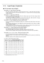
I/O Connector Input Signal
Terminal No. 14: Input Common (IN COM.)
• This is the terminal for input common. Connect this terminal to the “+” (plus) side of the control power
supply for NPN connection, and connect this terminal to the “-” (minus) side of the control power supply
for PNP connection.
Terminal No. 3: Trigger Input (TRIG.IN)
• This is the terminal of marking start signal. When the marking ready output is ON, the marking is started
on the edge of the trigger input ON signal.
Input TRIG. IN with holding the input status of the file selection (D0 to D6). (When the file No. changing
command (FNO) is set by RS-232C, input of D0 to D6 is not required.)
Terminal No. 4: Laser Radiation Stop Input (LASER STOP)
• This is the input terminal for stopping laser radiation. It is connected to the switch of the manual door of
the device.
When setting the state between the laser radiation stop input and terminal No. 15 OUT COM. into OPEN,
the laser radiation is stopped.
(When setting this state into OPEN during marking, the laser pumping is stopped. When setting this state
into OPEN during non-marking, the marking ready output becomes OFF.)
Terminal No. 17: Counter Reset Input (COUNTER RESET)
• This terminal sets the input to ON when resetting the counter.
Input COUNTER RESET with holding the input status of the file selection (D0 to D6).
(When the file No. changing command (FNO) is set by RS-232C, input of D0 to D6 is not required.)
Terminal No. 5, 6, 7, 8, 18, 19, 20: File Select Input (D0 to D6)
• These terminals select the file No. to be transferred into the head.
Specify the file No. (1 to 120) with D0 to D6. The file No. is specified with binary digit, and is selected by
ON/OFF.
Keep the input status of D0 to D6 while using the selected file.
The “File No.” correspondence table is as follows.
* The selectable file Nos. are from 1 to 120.
File No.
File No. in binary form
D6
D5
D4
D3
D2
D1
D0
001
0
0
0
0
0
0
1
002
0
0
0
0
0
1
0
003
0
0
0
0
0
1
1
004
0
0
0
0
1
0
0
005
0
0
0
0
1
0
1
006
0
0
0
0
1
1
0
007
0
0
0
0
1
1
1
008
0
0
0
1
0
0
0
••
•
••
•
118
1
1
1
0
1
1
0
119
1
1
1
0
1
1
1
120
1
1
1
1
0
0
0
Summary of Contents for LP-310
Page 5: ...5 MEMO ...
Page 21: ...21 MEMO ...
Page 26: ...26 MEMO ...
Page 30: ...30 MEMO ...
Page 33: ...33 MEMO ...
Page 87: ...87 MEMO ...
Page 125: ...125 MEMO ...
Page 137: ...137 MEMO ...
Page 149: ...149 MEMO ...
Page 155: ...155 4 External Control 4 1 Control Through I O Connector 156 4 2 Control with RS 232C 166 ...
Page 186: ...186 MEMO ...
Page 187: ...187 5 Troubleshooting 5 1 Troubleshooting 188 5 2 Measures for Indicated Error 189 ...
Page 191: ...191 6 Maintenance 6 1 Maintenance 192 ...
Page 193: ...193 7 Specification 7 1 Specification 194 7 2 Outer Dimensional Drawing 195 ...
Page 197: ...197 Appendix Character Code Table 198 Readable DXF File 207 Glossary 209 ...
Page 212: ...212 Index Index 213 ...
Page 215: ...No 9000 0062 20V ...


