168
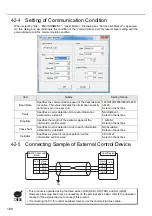
4-2-4 Setting of Communication Condition
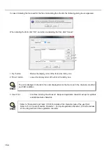
When selecting “File” - “ENVIRONMENT” - “Laser Marker”, the dialog box “Set Up Lser Marker” is appeared.
On this dialog box, accommodate the condition of the “communication port” for laser marker setting with the
external device and the communication condition.
4-2-5 Connecting Sample of External Control Device
Item
Outline
Setting Range
Baud Rate
Specifies the communication speed of the transmission/
reception. This value indicates the information capacity
sent/received in one second.
1200/2400/4800/9600/19200/
38400
Select in the list box.
Parity
Specifies an error detection bit to each information
delimited by a stop bit.
NA/Odd/Even
Select in the list box.
Stop Bits
Specifies the length of the delimiter signal of the
information sent/received.
1 bit/2 bit
Select in the list box.
Check Sum
Specifies an error detection code to each information
delimited by a delimiter.
NA/Available
Select in the list box.
Delimiter
Specifies a symbol of rough separation on the
information sent/received.
CR/CR+LF
Select in the list box.
•
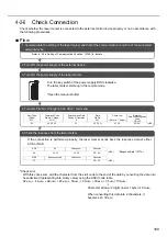
This product is operated using the three wires of RD (RXD), SD (TXD), and SG (GND).
However, since loop back may be necessary on the external device side, refer to the operation
manual of the external device to connect this product.
•
If connecting the PC for control and laser marker, use the commercial cross cable.
RS-232C Connector
(Head)
GND
TXD
RXD
GND
TXD
RXD
Signal
Name
5
3
2
Pin No.
Host Device
5
3
2
F.G.
Pin No.
Signal
Name
CHECK
Summary of Contents for LP-310
Page 5: ...5 MEMO ...
Page 21: ...21 MEMO ...
Page 26: ...26 MEMO ...
Page 30: ...30 MEMO ...
Page 33: ...33 MEMO ...
Page 87: ...87 MEMO ...
Page 125: ...125 MEMO ...
Page 137: ...137 MEMO ...
Page 149: ...149 MEMO ...
Page 155: ...155 4 External Control 4 1 Control Through I O Connector 156 4 2 Control with RS 232C 166 ...
Page 186: ...186 MEMO ...
Page 187: ...187 5 Troubleshooting 5 1 Troubleshooting 188 5 2 Measures for Indicated Error 189 ...
Page 191: ...191 6 Maintenance 6 1 Maintenance 192 ...
Page 193: ...193 7 Specification 7 1 Specification 194 7 2 Outer Dimensional Drawing 195 ...
Page 197: ...197 Appendix Character Code Table 198 Readable DXF File 207 Glossary 209 ...
Page 212: ...212 Index Index 213 ...
Page 215: ...No 9000 0062 20V ...

