35
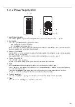
1-2-2 Power Supply BOX
1. Main Power Indicator
This indicator lights up in green when turning ON the key switch, indicating the power is supplied.
2. Key Switch
This is the key switch for starting up the laser marker.
ON : Impossible to remove key switch
OFF : Possible to remove key switch
When turning OFF the power supply (not activating laser marker), remove the key switch, and the removed
key switch shall be kept by the laser safety manager.
3. Interlock Connector
Use this part as the interlock connector to build up the interlock system. Removing this connector stops supplying
the power to the laser of the head.
(Opening both Pin 1 and Pin 3 stops the power, and connecting these pins supplies power.)
4. Frame Ground: F.G.
This is the terminal for grounding.
Be sure to ground this product either by this terminal or earth terminal of the inlet.
5. Inlet
With this inlet, the AC power supply is connected. Use the attached AC power cable.
90V to 132V AC or 180V to 264V AC (inc/-10% voltage fluctuations), 50/60Hz (Voltage and frequency
are switched automatically.)
The voltage of the attached AC power cable is 125V rating for LP-310/310-A, 250V rating for LP-310-C.
Be sure to connect the ground pin of the AC power cable to earth permanently.
6. Power Connector
This is the connector for supplying power to the head. Connect the attached head power cable.
7. Fuse
This is the fuse for protecting this product from overcurrent.
1
2
3
5
4
6
7
Summary of Contents for LP-310
Page 5: ...5 MEMO ...
Page 21: ...21 MEMO ...
Page 26: ...26 MEMO ...
Page 30: ...30 MEMO ...
Page 33: ...33 MEMO ...
Page 87: ...87 MEMO ...
Page 125: ...125 MEMO ...
Page 137: ...137 MEMO ...
Page 149: ...149 MEMO ...
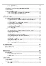
Page 155: ...155 4 External Control 4 1 Control Through I O Connector 156 4 2 Control with RS 232C 166 ...
Page 186: ...186 MEMO ...
Page 187: ...187 5 Troubleshooting 5 1 Troubleshooting 188 5 2 Measures for Indicated Error 189 ...
Page 191: ...191 6 Maintenance 6 1 Maintenance 192 ...
Page 193: ...193 7 Specification 7 1 Specification 194 7 2 Outer Dimensional Drawing 195 ...
Page 197: ...197 Appendix Character Code Table 198 Readable DXF File 207 Glossary 209 ...
Page 212: ...212 Index Index 213 ...
Page 215: ...No 9000 0062 20V ...


