58
2-2
Setting Procedure for Basic Function
The setting method for function to be applied to the actual marking is described in this section using sample.
2-2-1 Mark Counter
■
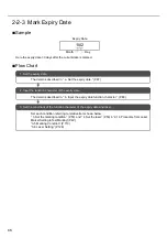
Sample
Set the counter shown above.
■
Flow Chart
0001
0002
0003
0998
0999
1000
•••••••
0001
0002
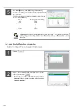
2. Input the function character of the counter.
The detail is described in “ b. Input the counter function character.” (P.60).
3. Set the conditions of the function character of the counter and laser.
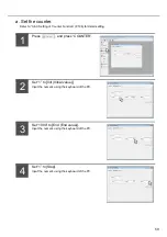
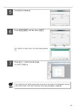
1. Set the counter.
The detail is described in “ a. Set the counter.” (P.59).
Set each condition referring to relative item shown below:
“ 3. Set the marking condition.” (P.50) and “ 4. Set the laser.” (P.53) in “2-1-3 Procedure from Laser
Marker Setting to Test Marking”
“3-5 Marking Condition” (P.110)
“3-6 Laser Setting” (P.126)
Summary of Contents for LP-310
Page 5: ...5 MEMO ...
Page 21: ...21 MEMO ...
Page 26: ...26 MEMO ...
Page 30: ...30 MEMO ...
Page 33: ...33 MEMO ...
Page 87: ...87 MEMO ...
Page 125: ...125 MEMO ...
Page 137: ...137 MEMO ...
Page 149: ...149 MEMO ...
Page 155: ...155 4 External Control 4 1 Control Through I O Connector 156 4 2 Control with RS 232C 166 ...
Page 186: ...186 MEMO ...
Page 187: ...187 5 Troubleshooting 5 1 Troubleshooting 188 5 2 Measures for Indicated Error 189 ...
Page 191: ...191 6 Maintenance 6 1 Maintenance 192 ...
Page 193: ...193 7 Specification 7 1 Specification 194 7 2 Outer Dimensional Drawing 195 ...
Page 197: ...197 Appendix Character Code Table 198 Readable DXF File 207 Glossary 209 ...
Page 212: ...212 Index Index 213 ...
Page 215: ...No 9000 0062 20V ...

