20
4.
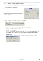
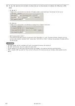
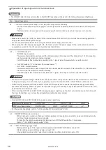
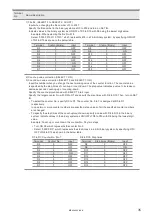
With DIP switch No. 5, select the setting method of the remote
mode.
DIP switch No. 5
Setting method of remote mode
ON
Use the input signal of REMOTE IN (A3) on I/O terminal.
OFF(initial setting)
Use the remote switch on the front of the controller.
Reference
•
When DIP switch No. 5 is ON, the remote switch on the controller is not available.
5.
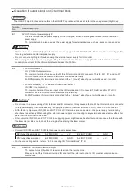
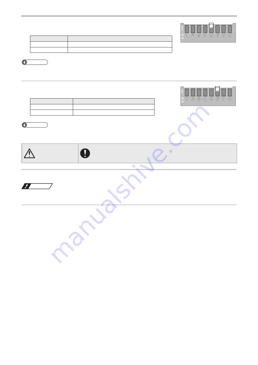
When DIP switch No. 5 is OFF, select the remote mode state at
powered ON with DIP switch No. 6.
DIP switch No. 6
Remote mode state at powered ON
ON
Starts up with remote mode ON
OFF (initial setting)
Starts up with remote mode OFF
Reference
•
When DIP switch No. 5 is ON, keep DIP switch No. 6 OFF.
•
When DIP switch No. 6 is ON, “X5: REMOTE IN” signal on I/O terminal is not available.
CAUTION
•
If the DIP switch No. 5 or No. 6 are used while turned on, construct a system
for re-pumping the laser manually as safety protection measures after the stop
of the laser radiation due to an emergency stop or an interlock.
6.
Install the DIP switch cover to the controller.
Notice
•
A plastic cover is installed on the DIP switch. Install this cover always to avoid the dust penetration to the controller.
7.
Turn ON the power of laser marker.
ME-LP400V-EX-6
Summary of Contents for LP-400 Series
Page 12: ...1 Before External Control ME LP400V EX 6...
Page 24: ...2 Control by I O ME LP400V EX 6...
Page 56: ...3 Control by Serial Communication RS 232 Ethernet ME LP400V EX 6...
Page 141: ...Troubleshooting ME LP400V EX 6...
Page 158: ...Character Code Table ME LP400V EX 6...
Page 176: ...Index ME LP400V EX 6...
Page 179: ...No 9000 0062 17V...
Page 180: ...Panasonic Industrial Devices SUNX Co Ltd 2003 2018 July 2018 9000 0062 17V...

