background image

46

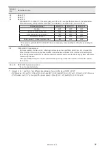
2-4  Timing Chart

Reference

• 

ON/OFF on the timing chart refers to ON/OFF operations. It does not refer to the voltage level (High/Low).

• 

In the following timing charts, the timing of output operation corresponding to the each input has a small delay of 0ms or 
more.

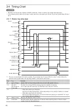
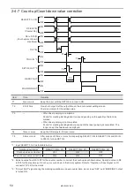
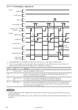
2-4-1  Basic input/output

T4

T5

T2

T3

T3

T1

ON

OFF

ON

OFF

ON

OFF

ON

OFF

[Input]

[Output]

Key switch

READY OUT

MARKING OUT

MARK END OUT

REMOTE OUT

LASER OUT

LASER IN

TRIG. IN

Shutter Status *1

(Open)

(Open)

(Close)

(Close)

Remote mode

ALARM OUT

(Active Low)

WARNING OUT

(Active Low)

SHUTTER IN

*1  :  There is no output signal for shutter operation. There is delay time of around 200ms to max. 1 second before the 

shutter actually opens/closes after inputting ON/OFF of the shutter control input.

Item

Time

Remarks

T1

approx. 75 sec. System Starting Time. Change to the remote mode after system start-up.

T2

about 20 
seconds/about 
15 seconds

The time from turning ON the pumping input to completion of pumping.
LP-V series: about 20 seconds, LP-400/LP-W series: about 15 seconds

T3

• 

When laser pumping is completed
Period for creating marking data. It varies depending on the quantity of data to be marked.

• 

When laser pumping is not completed
Period for creating marking data or period until the laser pumping is completed. The longer 
one of the two above is employed.

T4

10ms or more

Keep the ON status for 10ms or more.

T5

2 to 510ms

One-shot output. Set the output time on the environment setting screen. There is a small 

margin of error for the setting value.

ME-LP400V-EX-6

Summary of Contents for LP-400 Series

Page 1: ...2018 7 panasonic net id pidsx global Laser Marker External Control Manual LP 400 series LP V series LP W series ME LP400V EX 6 No 9000 0062 17V...

Page 2: ...5 Please remind that we assume no liability for any results arising out of operations regardless of the above clauses Disclaimer The applications described in this document are all intended for exampl...

Page 3: ...ctions to be observed This symbol is used to alert users to a specific operating procedure that must not be performed This symbols is used to alert users to a specific operating procedure that must be...

Page 4: ...cts subject to the local laws and regulations of the country or region in which this laser product is used To protect the operators eyes make it mandatory to wear goggles against laser beam within the...

Page 5: ...ring cable connecting and or maintenance work ensure that all the power switches are turned off Otherwise electrical shock may result The wiring and maintenance must be conducted by the electrical eng...

Page 6: ...ser beam is blocked by dust or gas it may cause decrease in laser marking or processing quality Installation and mounting Do not hold the cables and connectors at carrying this product Do not touch th...

Page 7: ...ed in the same raceway or connected in parallel to any device that generates high tension wires power lines large switching surge or the like There is a risk of malfunction caused by induction USB cab...

Page 8: ...xx T U A LP 410U C LP 410TU C LP 4xx T U C LP 410U CHN LP 410TU CHN LP 4xx T U CHN LP 435U LP 435TU LP 4xx T U LP 435 LP 4x5 LP 435U A LP 435TU A LP 4xx T U A LP 435U C LP 435TU C LP 4xx T U C LP 435U...

Page 9: ...ng method How to operate the laser marker and set the marking data using touch panel console or monitor and mouse Maintenance Troubleshooting External Control Manual This manual describes how to contr...

Page 10: ...5 2 1 1 I O terminal block 26 2 1 2 I O connector 26 2 1 3 Signals and details of I O terminal block 27 2 1 4 Signals and details of I O connector 33 2 2 Input Output Rating 40 2 2 1 Input rating and...

Page 11: ...unication Data Format 68 3 5 1 Command data 68 3 5 2 Response data 69 3 5 3 Communication sequence 72 3 6 Communication Command List 74 3 7 Command Description 78 Troubleshooting 141 Troubleshooting 1...

Page 12: ...1 Before External Control ME LP400V EX 6...

Page 13: ...ng to find the appropriate parameters or the maintenance work Run mode operation Run mode is an operation method to configure the settings of the laser marker by manual screen operation and to control...

Page 14: ...marking Turn on power with key switch on controller Edit the file Start test marking Save the file Edit and overwrite the file Start run operation Marking trigger input Select file to use in run oper...

Page 15: ...re the settings of the laser marker by manual screen operation and to control the marking start signal from the external devices such as switches or sensors connected to I O terminal 1 Set the marking...

Page 16: ...O connector A B C External control by serial communication commands RS 232C Ethernet Remote mode operation Controls the laser marker from external devices such as PLC using communication commands via...

Page 17: ...in advance before using external control Refer to 1 3 Before External Control P 18 Turn ON key switch of laser marker controller The device is ready for receiving the marking starting signal trigger...

Page 18: ...ition setting P 21 Refer to 1 3 3 Shift to remote mode P 23 Remote mode ON Communication environment setting Turn ON laser marker DIP switch setting Control by serial communication commands I O contro...

Page 19: ...LP W series DIP switch 3 With DIP switch No 2 select the control method I O or command for some specific operations DIP switch No 2 Control method for specific operations ON Control by serial communi...

Page 20: ...N Starts up with remote mode ON OFF initial setting Starts up with remote mode OFF Reference When DIP switch No 5 is ON keep DIP switch No 6 OFF When DIP switch No 6 is ON X5 REMOTE IN signal on I O t...

Page 21: ...output duration for some signals such as MARK END OUT and SET OK OUT Setting range 2 ms to 510 ms initial value is 40 ms Detect TRIG Warning during Marking Configure if you will output ON or will not...

Page 22: ...barcode GS1 Data Matrix is used To set the barcode character by using serial communication command BCS select either GS OFF or FNC1 ON as the separator of AI data with the variable length Reference Th...

Page 23: ...nal Turn ON the REMOTE IN A3 of the I O terminal on the rear of the controller A3 REMOTE IN Check that DIP switch No 5 is ON Refer to 1 3 1 DIP switch setting P 19 Reference When DIP switch No 5 is ON...

Page 24: ...2 Control by I O ME LP400V EX 6...

Page 25: ...input output for data configuration such as selecting a file number and the input output for the specific functions Reference Before using I O configure the DIP switch and the environment settings Re...

Page 26: ...follows When the terminal block is removed Laser marker side connector type Female D sub 25 pin Screw type M2 6 female User side connector type Male D sub 25 pin Screw type M2 6 male 2 1 2 I O connec...

Page 27: ...OUT Remote mode output B4 22 READY Marking ready output B5 21 MARKING Marking output B6 20 MARK END Marking end output B7 19 LASER OUT Laser pumping completion output B8 18 WARNING Warning output B9...

Page 28: ...y For PNP models this terminal is connected to the plus side of power which is used for control Notice Do not invert the power wiring of I O terminal and I O connector It may cause a failure When this...

Page 29: ...r A10 N C No connection Do not use this terminal A11 For NPN models 1 LASER STOP Output common for laser stop This terminal is connected to OUT COM B2 internally Connect A11 with LASER STOP A12 to rel...

Page 30: ...1 IN COM Input common The common terminal for each input of the I O terminal and I O connector This B2 and No 37 of I O connector are the common terminals connected internally For PNP models this ter...

Page 31: ...e to the alarm this MARK END turns ON This is one shot output Reference READY OUT B4 is output even during one shot output of marking end output MARK END B6 is output even when marking is interrupted...

Page 32: ...terminals B12 EMER Emergency stop input Use this terminal to stop the laser radiation or disable the laser radiation by connecting with the safety devices such as a door or a switch When between EMER...

Page 33: ...D 2 Counter 2 end output 35 CEND 3 GAP OUT Counter 3 end output Date gap output 36 SET OK Setting completion output 37 For NPN models 1 OUT COM Output common For PNP models C 1 IN COM Input common 1 S...

Page 34: ...may cause a failure When IN COM and OUT COM in the I O terminal are connected to the power supply it is not necessary to supply the power to IN COM or OUT COM in I O connector 2 SET IN Turn on this s...

Page 35: ...ue to increase or decrease per one counting up or counting down Specify the count up count down with SELECT 0 to 2 input Specify the target counter No with D0 to D7 and specify the step times with D8...

Page 36: ...em as D0 to D15 and turn on SET IN No 2 The data numbers corresponding to D0 to D15 are defined as follows according to the settings I O input condition settings Terminal Data number target Data numbe...

Page 37: ...me hold input Performs marking of date and lot reflecting the time when the input TIME HOLD No 23 is turned ON While this input is turned on the laser marker retains the time and date of the internal...

Page 38: ...nged passed the midnight while the input TIME HOLD No 23 is ON This is the output to notify you that the laser marker is marking the different date from that of the internal clock while TIME HOLD No 2...

Page 39: ...2 of I O terminal are the common terminals connected internally For PNP models this terminal is connected to the minus side of power which is used for control Notice Do not invert the power wiring of...

Page 40: ...C LP VxxU C Input Input common IN COM External power 24V DC NPN open collector output Each input Input Input common IN COM External power 24V DC PNP open collector output Each input Notice This produc...

Page 41: ...VxxU A LP W series For PNP models LP 4xx T U C LP 4xxS9 T U C LP VxxU C Output common OUT COM External power 30V DC MAX Each output Load Output Output common OUT COM External power 30V DC MAX Load Ea...

Page 42: ...T COM B12 EMER B11 EMER A12 LASER STOP A11 LASER STOP Notice Short circuiting IN COM and OUT COM in supplying power might cause the short out and also cause the trouble with the laser marker IN COM an...

Page 43: ...and OUT COM in supplying power might cause the short out and also cause the trouble with the laser marker IN COM and OUT COM on the I O terminal block are connected with IN COM and OUT COM on the I O...

Page 44: ...ntrolled by external devices LP 4xx T U LP 4xx T U A LP 4xxS9 T U LP 4xxS9 T U A LP VxxU LP VxxU A LP W series A7 LASER IN B2 OUT COM A2 IN COM A4 TRIG IN PLC B3 REMOTE OUT B9 ALARM A8 SHUTTER B4 READ...

Page 45: ...emergency stop function Opening between B12 A2 turns off the laser pumping and marking is disabled Connect A12 LASER STOP to A2 OUT COM to release the laser stop function Opening between A12 A2 closes...

Page 46: ...shutter actually opens closes after inputting ON OFF of the shutter control input Item Time Remarks T1 approx 75 sec System Starting Time Change to the remote mode after system start up T2 about 20 se...

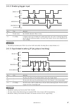
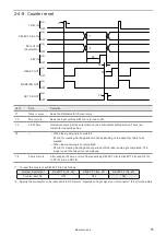
Page 47: ...3 Equidistant marking Flying object marking ON OFF ON OFF ON OFF ON OFF T2 T2 T2 T3 T3 T3 T3 T1 READY OUT TRIG IN MARKING OUT MARK END OUT Item Time Remarks T1 The time when the work travels the dista...

Page 48: ...Period for creating marking data It varies depending on the quantity of data to be marked When laser pumping is not completed Period for creating marking data or period until the laser pumping is com...

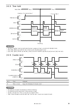
Page 49: ...e time is held in spite of switching the file No If the TIME HOLD ON OFF is switched in short time each ON OFF hold time should be more than 2 seconds 2 4 6 Counter end T1 T1 T1 T1 ON OFF ON OFF ON OF...

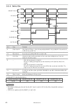
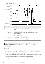
Page 50: ...data or period until the laser pumping is completed The longer one of the two above is employed T4 10ms or more Keep the ON status for 10ms or more T5 0 5ms or more After a lapse of 0 5ms or more fro...

Page 51: ...mpleted Period for creating marking data It varies depending on the quantity of data to be marked When laser pumping is not completed Period for creating marking data or period until the laser pumping...

Page 52: ...No 21 SELECT 2 No 22 Data No of rank external offset ON OFF OFF 2 Specify the data number of rank external offset function by using D0 to D15 Refer to Operation of input signal on I O connector P 34 R...

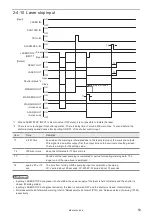
Page 53: ...laser stop input the mark end outputs This signal is a one shot output Set the output time on the environment setting screen There is a margin for the setting value T2 100ms or more Keep the ON statu...

Page 54: ...0ms or more Keep the ON status for 100ms or more T2 Period until the laser pumping is completed or period for creating marking data The longer one of the two above is employed T3 approx 20 or 15 sec T...

Page 55: ...o OPEN Laser Pumping OFF Internal Shutter CLOSE Status Alarm E004 2 Close Emergency Stop and input alarm reset Push Emergency stop switch Laser Pumping OFF Internal Shutter CLOSE Status Alarm E002 2 P...

Page 56: ...3 Control by Serial Communication RS 232 Ethernet ME LP400V EX 6...

Page 57: ...control method for Laser Control and Shutter Control should be selected from either the serial communication or I O Turn the No 2 DIP switch on the back surface of controller before turning on the po...

Page 58: ...available RS 232C cable connect only 3 signals of RxD TxD and GND and do not use other signals on the laser marker side The external controller may need a signal line connection loop back line other...

Page 59: ...Odd initial setting None Stop bits 1 bit 2 bit initial setting 1 bit Flow control None Check sum OFF ON initial setting OFF Delimiter CR CR LF initial setting CR Start code Setting request Reading re...

Page 60: ...255 255 255 254 Initial value 255 255 255 0 Default gateway 1 0 0 0 to 223 255 255 255 1 Initial value Unspecified Port 5001 to 65534 except 9090 9091 Initial value 9094 Start code Setting request Re...

Page 61: ...any through a HUB or a router Use a HUB or a router that supports 1000BASE T 100BASE TX 10BASE T and Category 5e or higher straight cables for connection HUB or router Straight cable External control...

Page 62: ...ge specified with a number FNO File change specified with a comment FNN Shutter close only SHT Command reception permission MKM Laser pumping LSR Counter reset CTR Status request STS Marking trigger M...

Page 63: ...s in the ASCII code 02 HEX 46 HEX 4E HEX 4F HEX 53 HEX 32 HEX 30 HEX 34 HEX 37 HEX 205 HEX 30 35 HEX is the value converted the lower two digits character lower one byte 05 HEX into two characters in...

Page 64: ...conditions setting Various command 12 Command reception mode OFF MKM command 13 Shutter setting close SHT command 14 Laser pumping OFF LSR command When 10 Command reception mode ON is transmitted the...

Page 65: ...command or STR command 8 Command reception mode OFF MKM command 9 Shutter setting close SHT command 10 Laser pumping OFF LSR command Send STS command again after a while To memorize the last marked ch...

Page 66: ...ommand again after a while Select the file in that Serial data marking function is set READY ON Yes To finish the marking Change the character No Send the character data to be marked Reference For usi...

Page 67: ...hing File No specified FNO command 3 Shutter setting open SHT command 4 Status request STS command 7 Shutter setting close SHT command 8 Laser pumping OFF LSR command 5 Marking trigger MRK command 6 C...

Page 68: ...of setting data Read Note S or R cannot be selected for some commands Data Data specified per command The content to be specified varies per command Refer to 3 7 Command Description P 78 Check sum 1...

Page 69: ...acters single character Head End Code Description Start code ACK code 06 HEX fixed A start code is a code to identify the data head and to indicate that the data is a response data for normal receivin...

Page 70: ...r warning occurs 11 SIN command is not acceptable because of following conditions Internal shutter status is closed No setting of Serial data input on character string 12 The file cannot be saved due...

Page 71: ...command Refer to 3 7 Command Description P 78 Check sum 1 Check sum indicates the lower 1 byte of adding result of value binary from the start code to the last data by converting it to two characters...

Page 72: ...wn below Laser marker Readout response Transmission Reception Reception Transmission Command Readout of setting data External device Communication sequence at abnormal data setting operation instructi...

Page 73: ...d during marking operation Warning occurred according to the setting of marking condition during marking operation Shutter open command Shutter close command External device Communication sequence whe...

Page 74: ...ecifies the file No to change the file P 83 File change Comment specified FNN Specifies the file name comment to change the file P 83 File overwriting registration FOR Overwrite and register the file...

Page 75: ...S code For characters including control code specified with 2 bytes alternate codes KANA KANJI and function characters P 96 Bar code marking condition BRF Sets the marking condition for bar code and 2...

Page 76: ...at to mark the same marking contents on multiple locations in one file P 126 Step repeat fine adjustment SRA Sets the fine adjustment of Step Repeat to mark the same marking contents on multiple locat...

Page 77: ...ENC Sets the encoder pulse value for use of the encoder in flying object marking P 136 Maintenance Laser check radiation SPT Controls Laser Check Radiation for laser radiation at the center of the mar...

Page 78: ...iter Name Data length byte Description Remarks Command reception mode 1 0 Reception mode ON Start command reception in the marking ready OFF status 1 Reception mode OFF Finish command reception and re...

Page 79: ...eries and about 15 seconds for LP 400 LP W series from turning ON the laser pumping to the completion of pumping Shutter SHT Controls the internal shutter opening closing Setting of shutter STX SHT S...

Page 80: ...leted Command reception status 1 0 Shutter close or command reception mode ON including while the shutter is opened 1 Shutter open excepting when the command reception mode is ON Shutter and command r...

Page 81: ...d Data transmission after setting marking status transmission permission The status which shows if the marking operation is normally finished is transmitted when receiving a marking trigger from I O o...

Page 82: ...trigger type When this command is sent when the marking trigger cannot be accepted Ready is OFF abnormal receiving response is returned from laser marker Guide laser control GID Controls radiation of...

Page 83: ...e the file Change file No Changes file No according to the file name comment STX FNN S File name Max 20 byte Check sum Delimiter Name Data length byte Description Remarks File name Max 20 Specify the...

Page 84: ...me STX FNM Sub command File name Max 20 byte Check sum Delimiter Sub command is S at the time of setting and A for response data at the time of readout Readout request of file name STX FNM R Check sum...

Page 85: ...dout data includes characters that cannot be expressed in ASCII code such as Katakana and Kanji 2 byte character only these 2 byte characters are read out in shift JIS code In this case the maximum re...

Page 86: ...sed in case of no offset Z Counter numbering system 1 1 to 9 A to Z This letter is not used when decimal number is used 0N XnY Z with zero N XnY Z without zero justify INP n Rank _N XnY Z right aligne...

Page 87: ...rial data input For resetting the data set the reception mode ON for command reception permission MKM command or close the shutter SIN command cannot be used with the rank function external offset and...

Page 88: ...ime Remarks T1 1 second or more SIN command cannot be sent until the shutter opens The shutter opens approx 1 second after the shutter open input T2 0 ms or more After confirming the marking output is...

Page 89: ...king character string Max 21 byte Check sum Delimiter Sub command is S at the time of setting and A for response data at the time of readout Readout request of rank character string STX RKS R Data No...

Page 90: ...ck sum Delimiter Name Data length byte Description Remarks Counter No 1 0 7 4 7 common counter Current value 6 000000 999999 No minus number Initial value 6 000000 999999 End value 6 000000 999999 Ste...

Page 91: ...cember 31 2099 Setting Readout data of expiry date time condition STX LMT Sub command Expiry No Expiry Reference unit Start date 7 byte Check sum Delimiter Sub command is S at the time of setting and...

Page 92: ...TC R Lot No 1 byte Check sum Delimiter Name Data length byte Description Remarks Lot No 1 0 7 4 7 common lot Lot target 2 00 current 01 08 expiry 1 to 8 10 17 counter 0 to 7 The unit of period to swit...

Page 93: ...nter 01 60 The setting range varies depending on the condition of period unit Start period 6 Period condition Setting range Year week based year 198000 209900 Month 000001 000012 Day 000001 000031 Y M...

Page 94: ...e lines data in each line are jointed in the order of line numbers and they are coded as the data in one line No line break is inserted for each line When setting bar code marking data in multiple lin...

Page 95: ...No line break is inserted for each line When setting bar code marking data in multiple lines the total input data should be 255 characters or less If readout data includes function characters such as...

Page 96: ...line No line break is inserted for each line When setting bar code marking data in multiple lines make sure the sum of all barcode data is 255 characters or less If readout data includes function cha...

Page 97: ...iption Remarks Bar code No 1 0 7 Area No 1 0 9 A F Specifies which area part is the marking position of the concatenated marking on the flying object In case of marking static object specify 0 Code ty...

Page 98: ...square Number of column 2 00 10 80 Combination of number of row and column is limited 1 Number of module in X direction Specifying 00 for number of both row and column encodes with the minimum size s...

Page 99: ...0 001 000 110 000 LP 4x5 LP V15 001 000 160 000 LP 4x1 LP W 001 000 055 000 Narrow element 5 0 050 1 000 mm Indicates the width of narrow element of bar and space Set the larger value than Line width...

Page 100: ...e Set the larger value than Line width in laser setting screen X position 8 Model type Setting range mm LP V10 045 000 045 000 LP 4x0 055 000 055 000 LP 4x5 LP V15 080 000 080 000 LP 4x1 LP W 027 500...

Page 101: ...Invalid 2 Valid Inversion 1 0 Do not invert 1 Invert 2 Invert with guard pattern Bar code height 7 Model type Setting range mm LP V10 001 000 090 000 LP 4x0 001 000 110 000 LP 4x5 LP V15 001 000 160 0...

Page 102: ...acked One bar code height GS1 DataBar Stacked Omnidirectional 7 Model type Setting range mm LP V10 001 000 090 000 LP 4x0 001 000 110 000 LP 4x5 LP V15 001 000 160 000 LP 4x1 LP W 001 000 055 000 Sepa...

Page 103: ...001 000 160 000 LP 4x1 LP W 001 000 055 000 Separator height W 4 00 0 10 0 Ratio of separation pattern height to width Symbol char in row 2 02 20 Only even value applied Number of Symbol Character in...

Page 104: ...ert 1 Invert Bar code height 7 Model type Setting range mm LP V10 001 000 090 000 LP 4x0 001 000 110 000 LP 4x5 LP V15 001 000 160 000 LP 4x1 LP W 001 000 055 000 Narrow element 5 0 050 1 000 mm Set t...

Page 105: ...text CC B Composite 1D part 50 GS1 DataBar STD Truncated 51 GS1 DataBar Stacked 52 GS1 DataBar Stacked Omnidirectional 53 GS1 DataBar Limited 54 GS1 DataBar Expanded 55 GS1 DataBar Expanded Stacked 56...

Page 106: ...ut 12 digit excepting a check digit EAN JAN 13 Input 7 digit excepting a check digit EAN JAN 8 Input 11 digit excepting a check digit UPC A Input 6 digit excepting a check digit UPC E 2 The number of...

Page 107: ...side of Composite code When the code type is other than the Composite code select 1 X position 8 Model type Setting range mm LP V10 045 000 045 000 LP 4x0 055 000 055 000 LP 4x5 LP V15 080 000 080 000...

Page 108: ...break part conforms with the line number of the bar code data Line interval 7 Model type Setting range mm LP V10 000 000 090 000 LP 4x0 000 000 110 000 LP 4x5 LP V15 000 000 160 000 LP 4x1 LP W 000 00...

Page 109: ...s Bar code No 1 0 7 Pattern type 1 QR code 0 Margin 1 Dark Module 2 Light Module 3 Alignment 4 Finder Data Matrix code 0 Quiet Zone 1 Mark Module 2 Space Module Character code 4 0000 2230 2239 or 8121...

Page 110: ...nded The logo file name corresponding to the specified number is indicated The logo file setting will be deleted when no file name is specified in this command For VEC file the extension can be omitte...

Page 111: ...A F Specifies which area part is the marking position of the concatenated marking on the flying object In case of marking static object specify 0 X scale 8 0010 000 1000 000 Y scale 8 X position 8 300...

Page 112: ...is the marking position of the concatenated marking on the flying object In case of marking static object specify 0 Origin position 1 0 Center 1 Left bottom 2 Right bottom 3 Left top 4 Right top 5 Ori...

Page 113: ...nothing should be input in Laser Pulse Cycle Correction Scan speed correction 3 005 500 Laser pulse cycle correction Only for LP V series 3 050 200 For the detail of the model type refer to Target la...

Page 114: ...g range mm LP V10 045 000 045 000 LP 4x0 055 000 055 000 LP 4x5 LP V15 080 000 080 000 LP 4x1 LP W 027 500 027 500 Y coordinate of start point 8 X coordinate of end point 8 Y coordinate of end point 8...

Page 115: ...part 7 Model type Setting range mm LP V10 000 010 090 000 LP 4x0 000 010 110 000 LP 4x5 LP V15 000 010 160 000 LP 4x1 LP W 000 010 055 000 Set the larger value than Line width in laser setting screen...

Page 116: ...80 under 1 180 more Dashed line Length of solid part 7 Model type Setting range mm LP V10 000 010 090 000 LP 4x0 000 010 110 000 LP 4x5 LP V15 000 010 160 000 LP 4x1 LP W 000 010 055 000 To make it no...

Page 117: ...limiter Name Data length byte Description Remarks Processing condition No 1 0 7 Area No 1 0 9 A F Specifies which area part is the marking position of the concatenated marking on the flying object In...

Page 118: ...diation condition No Line No 5 byte Check sum Delimiter Readout data STX PRD A Point radiation condition No Line No Radiation time Laser power correction X position Y position Max 31 byte Check sum De...

Page 119: ...f processing condition STX PRF R Point radiation condition No 2 byte Check sum Delimiter Name Data length byte Description Remarks Point radiation condition No 2 00 15 System reservation 1 0 fixed Sys...

Page 120: ...overwriting marking is set Mirror Y axis symmetry 1 0 inversion OFF 1 inversion ON The character marked is inverted to the Y axis Flip X axis symmetry 1 0 inversion OFF 1 inversion ON The character ma...

Page 121: ...yte Description Remarks Condition No 2 01 60 X position 8 When the marking form is other than fan like Model type Setting range mm LP V10 045 000 045 000 LP 4x0 055 000 055 000 LP 4x5 LP V15 080 000 0...

Page 122: ...ition No 2 01 60 Area No 1 0 9 A F Specifies which area part is the marking position of the concatenated marking on the flying object In case of marking static object specify 0 Start line 2 01 60 row...

Page 123: ...P 4x1 LP V15 0 000 4 000 LP 4x0 LP 4x5 0 000 6 000 Laser power correction 3 000 200 The correction ratio is calculated using the value set at the laser setting as 100 With LP 400 LP W series nothing s...

Page 124: ...ng for marking is indicated Angle of character interval 7 180 00 180 00 The angle between the center of character and the center of next character is indicated Font No 1 1 character font 1 2 character...

Page 125: ...witch coordinates using I O input Setting Readout data of external offset coordinates STX OFS Sub command Parallel data No X offset Y offset offset 26 byte Check sum Delimiter Sub command is S at the...

Page 126: ...5 000 The marking pitch to the Y direction is specified Column step 7 The marking pitch to the X direction is specified X offset 8 Model type Setting range mm LP V10 045 000 045 000 LP 4x0 055 000 055...

Page 127: ...99 Fine adj type 1 0 Setting deletion Number of delete line 3 001 100 If only the first line in the list line will be deleted the setting can be omitted 2 In case of Single as fine adjustment type da...

Page 128: ...r all columns 4 fine adjustment for all rows 5 fine adjustment for column 6 fine adjustment for row Target column or row 3 001 100 Sets target column s or row s for fine adjustment In case of fine adj...

Page 129: ...0 0 Set by increment of 0 5 Scan speed SSP Sets the scan speed of the laser Setting Readout data of scan speed STX SSP Sub command Scan speed 5 byte Check sum Delimiter Sub command is S at the time of...

Page 130: ...imiter Name Data length byte Description Remarks Laser pulse cycle 4 10 0 50 0 ms CW pulse cycle duty CWL Supported models LP W series Adjust the laser pulse cycle and duty of LP W series Setting Read...

Page 131: ...he width necessary to avoid crossing at marking intersection and marking pitch of the bold characters and bar code Setting Readout data of line width and marking pitch STX WDC Sub command Line width M...

Page 132: ...timing of starting laser is adjusted Adjustment of ending point 4 100 100 The timing of stopping laser is adjusted Edge adjustment 3 000 100 The wait at edge is adjusted Curve adjustment 3 000 100 The...

Page 133: ...condition STX TRG R Check sum Delimiter Name Data length byte Description Remarks Moving direction 1 0 still 1 left 2 right 3 front 4 back The moving direction of line at marking to flying object is...

Page 134: ...the trigger input is displayed When the moving speed is other than still delay distance is shown and the distance where the marking starts after the trigger input is displayed Marking interval INT Set...

Page 135: ...d LSP Sets the line speed in flying object marking Setting Readout data of line speed STX LSP Sub command Line speed 7 byte Check sum Delimiter Sub command is S at the time of setting and A for respon...

Page 136: ...he internal shutter is automatically opened and closed at the time of start and stop of radiation Stop radiation temporarily refers to the status stopping radiation with the shutter opened Use this st...

Page 137: ...wer correction Reference The power check command is rejected when the DIP switch No 2 in the rear side of the laser marker is set to OFF Transmit the power check command with laser pumping turned ON a...

Page 138: ...rection date 14 For 15 00 00 on April 1 2012 20120401150000 When the power correction has not been performed this value is 00000000000000 Total laser radiation time 9 0000000 0 1000000 0 h Reference P...

Page 139: ...year 4 1980 2037 year Month 2 01 12 month Day 2 01 31 day Hour 2 00 23 hour Minute 2 00 59 minute Second 2 00 59 second Reference The setting changed by this command is saved without overwriting Era...

Page 140: ...Reference The setting changed by this command is saved without overwriting I O environment ENV Sets the operating environment of the I O terminal and I O connector Setting Readout data of I O environm...

Page 141: ...Troubleshooting ME LP400V EX 6...

Page 142: ...ly or supply power from outside Emergency stop input on I O terminal is in OPEN status or safety equipment such as door and switch connected to the Emergency stop input on I O terminal is in OPEN stat...

Page 143: ...hows nothing Monitor is not turned on Check power to monitor Monitor cable is not connected Check that monitor cable is securely connected to connector VGA OUT on back of controller VGA compatible mon...

Page 144: ...tput power of laser marker Applicable marking object is as follows FAYb laser marker LP V LP W series Metal resin excluding transparent and translucent types CO2 laser marker LP 400 series Resin inclu...

Page 145: ...ies only Contact our sales office Fumes occurring during marking hinder laser beam Install dust collector Check that dust collector works well Distance to object is not appropriate Adjust distance bet...

Page 146: ...e are continuous vibrations coming from surrounding equipment such as motor and press Perform vibration prevention measures There are irregular vibrations coming from surrounding equipment such as air...

Page 147: ...ion of conveyor Secure objects to prevent misalignment Marking character pitch is unstable The line speed at the marking position is different from the speed at the installation site of the encoder Pl...

Page 148: ...S 232C or Ethernet port They cannot be used at the same time or switched The port selected in the environment setting screen indicates the valid communication port RS 232C is selected at factory shipm...

Page 149: ...not pumped Internal shutter is closed Open the internal shutter When controlling the shutter by I O signal turn off DIP switch No 2 and turn on terminal SHUTTER in terminal block When controlling the...

Page 150: ...r occurs All commands except the following are refused while alarm or error is active When alarm occurred Status Request STS Error code ECR When warning occurred Status Request STS Error code ECR Shut...

Page 151: ...E Error details Measures E002 Emergency stop button of controller is pushed Release emergency stop button of controller by turning it in arrow direction E004 Emergency stop occurred on external termin...

Page 152: ...s an unnecessary short line segment in logo files Set scan speed smaller or 0 to Pre Scan time on Laser Setting E240 E241 The temperature of the laser has reached its limit Check that the ambient temp...

Page 153: ...marker When not recovered contact to our sales office E450 to E456 Memory error E700 Unable to lase as laser pumping is turned OFF Confirm that the laser pumping remains on during lasing operation Che...

Page 154: ...d on and then open the internal shutter ERROR CODE Error details Measures E251 Detected a decrease in clock battery voltage Reset present time Contact to our sales office While laser Marker power is o...

Page 155: ...a start point and a end point of characters or logo data Separate the long segment into short data E620 E621 Flying object area over Can not follow line speed of flying object marking Shorten marking...

Page 156: ...is turned OFF Turn ON the laser pumping and after the laser pumping has completed start marking E701 1 Started laser power check in laser pumping OFF state Turn ON the laser pumping and after the lase...

Page 157: ...the narrow element basic module larger than that of the line width of the laser E913 No quiet zone in bar code Set the proper value for Quiet Narrow Ratio With the inversion setting set always quiet...

Page 158: ...Character Code Table ME LP400V EX 6...

Page 159: ...input the control codes in the barcode 2D code strings set the code data as follows The following control codes EOT FS GS RS or US you can set with BBS or SIN command by using ASCII code In this case...

Page 160: ...81CE 2250 81DE 2260 81FE 2270 Alpha numeric 824F 2330 825F 2340 826F 2350 8280 2360 8290 2370 JIS code 2121 is a blank character space and any characters are not registered into the blank The followi...

Page 161: ...836F 2550 8380 2560 8390 2570 Greek character 839E 2620 83AE 2630 83BE 2640 83CE 2650 Russian character 843F 2720 844F 2730 845F 2740 846F 2750 8480 2760 8490 2770 889E 3020 88AE 3030 88BE 3040 88CE...

Page 162: ...20 8B4F 3530 8B5F 3540 8B6F 3550 8B80 3560 8B90 3570 8B9E 3620 8BAE 3630 8BBE 3640 8BCE 3650 8BDE 3660 8BEE 3670 8C3F 3720 8C4F 3730 8C5F 3740 8C6F 3750 8C80 3760 8C90 3770 8C9E 3820 8CAE 3830 8CBE 38...

Page 163: ...50 8EDE 3C60 8EEE 3C70 8F3F 3D20 8F4F 3D30 8F5F 3D40 8F6F 3D50 8F80 3D60 8F90 3D70 8F9E 3E20 8FAE 3E30 8FBE 3E40 8FCE 3E50 8FDE 3E60 8FEE 3E70 903F 3F20 904F 3F30 905F 3F40 906F 3F50 9080 3F60 9090 3F...

Page 164: ...80 4360 9290 4370 929E 4420 92AE 4430 92BE 4440 92CE 4450 92DE 4460 92EE 4470 933F 4520 934F 4530 935F 4540 936F 4550 9380 4560 9390 4570 939E 4620 93AE 4630 93BE 4640 93CE 4650 93DE 4660 93EE 4670 94...

Page 165: ...30 95BE 4A40 95CE 4A50 95DE 4A60 95EE 4A70 963F 4B20 964F 4B30 965F 4B40 966F 4B50 9680 4B60 9690 4B7O 969E 4C20 96AE 4C30 96AE 4C30 96AE 4C30 96BE 4C40 96BE 4C40 96CE 4C50 96DE 4C60 96EE 4C70 973F 4D...

Page 166: ...166 Shift JIS JIS 0 1 2 3 4 5 6 7 8 9 A B C D E F 983F 4F20 984F 4F30 985F 4F40 986F 4F50 ME LP400V EX 6...

Page 167: ...030 98AE 5030 98AE 5030 98BE 5040 98CE 5050 98DE 5060 98EE 5070 993F 5120 994F 5130 994F 5130 995F 5140 995F 5140 995F 5140 995F 5140 996F 5150 996F 5150 996F 5150 9980 5160 9980 5160 9980 5160 9990 5...

Page 168: ...BE 5440 9ACE 5450 9ADE 5460 9ADE 5460 9ADE 5460 9ADE 5460 9ADE 5460 9ADE 5460 9AEE 5470 9B3F 5520 9B4F 5530 9B5F 5540 9B6F 5550 9B6F 5550 9B6F 5550 9B80 5560 9B90 5570 9B90 5570 9B90 5570 9B90 5570 9B...

Page 169: ...60 9C90 5770 9C9E 5820 9CAE 5830 9CBE 5840 9CCE 5850 9CDE 5860 9CEE 5870 9CEE 5870 9D3F 5920 9D3F 5920 9D3F 5920 9D4F 5930 9D5F 5940 9D6F 5950 9D80 5960 9D90 5970 9D9E 5A20 9DAE 5A30 9DAE 5A30 9DBE 5A...

Page 170: ...4F 5D30 9F4F 5D30 9F5F 5D40 9F5F 5D40 9F5F 5D40 9F6F 5D50 9F6F 5D50 9F6F 5D50 9F6F 5D50 9F80 5D60 9F80 5D60 9F80 5D60 9F80 5D60 9F90 5D70 9F9E 5E20 9FAE 5E30 9FBE 5E40 9FCE 5E50 9FDE 5E60 9FEE 5E70 E0...

Page 171: ...6F 6150 E180 6160 E190 6170 E19E 6220 E19E 6220 E19E 6220 E19E 6220 E1AE 6230 E1AE 6230 E1AE 6230 E1BE 6240 E1CE 6250 E1DE 6260 E1DE 6260 E1DE 6260 E1DE 6260 E1EE 6270 E23F 6320 E23F 6320 E24F 6330 E2...

Page 172: ...30 E3AE 6630 E3BE 6640 E3BE 6640 E3BE 6640 E3CE 6650 E3CE 6650 E3DE 6660 E3DE 6660 E3DE 6660 E3EE 6670 E43F 6720 E44F 6730 E45F 6740 E45F 6740 E45F 6740 E45F 6740 E46F 6750 E46F 6750 E46F 6750 E480 67...

Page 173: ...70 E63F 6B20 E63F 6B20 E63F 6B20 E64F 6B30 E64F 6B30 E64F 6B30 E65F 6B40 E66F 6B50 E680 6B60 E690 6B70 E69E 6C20 E69E 6C20 E6AE 6C30 E6AE 6C30 E6AE 6C30 E6AE 6C30 E6BE 6C40 E6BE 6C40 E6CE 6C50 E6CE 6C...

Page 174: ...6F 6F50 E880 6F60 E890 6F70 E890 6F70 E89E 7020 E8AE 7030 E8AE 7030 E8AE 7030 E8BE 7040 E8CE 7050 E8CE 7050 E8CE 7050 E8CE 7050 E8DE 7060 E8DE 7060 E8DE 7060 E8DE 7060 E8EE 7070 E8EE 7070 E93F 7120 E9...

Page 175: ...EA80 7360 EA80 7360 EA90 7370 EA90 7370 EA90 7370 EA90 7370 EA9E 7420 User Registration Character Font The character which can be registered as a user s registration character is 50 kinds to 8121 815...

Page 176: ...Index ME LP400V EX 6...

Page 177: ...r 68 DIP switch 19 DXF Logo Condition CDD 112 E Emergency Stop Input 54 Encoder Signal ENC 136 Equidistant Marking Flying Object Marking 47 Era Year ERA 139 Error Indication 151 Ethernet 60 Expiry Dat...

Page 178: ...ormat 71 Reception time out 72 Remote Mode 23 Response Data 69 Response data format for abnormal receiving 70 Response data for normal receiving 69 RS 232C 57 Run mode 13 15 S Scan Speed SSP 129 Selec...

Page 179: ...No 9000 0062 17V...

Page 180: ...Panasonic Industrial Devices SUNX Co Ltd 2003 2018 July 2018 9000 0062 17V...

Reviews: