149
3.
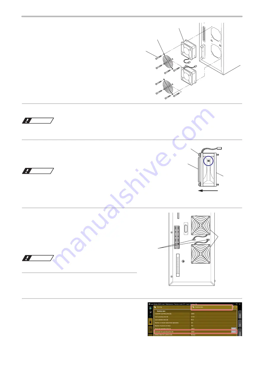
Loosen the screws (4 screws for 1 fan), and
remove the fan guard and the fan itself from
the controller.
4.
Remove dust and dirt adhered onto the fan by air-blowing.
ワㄐㄕㄊㄆ
• Do not rinse the fan. This may cause failure of the electronic parts inside.
5.
Install the fan guard against the direction of arrow on the
side of the fan indicating the air flow, as shown in the figure
on the right (exhaust direction).
ワㄐㄕㄊㄆ
• Install the controller fan in the direction so that the air flow matches the
exhaust direction.
Fan installed in the wrong way causes the flow to go in the wrong way,
which may failure of the product.
6.
Install the fan so that the fan cable will be routed
in the place as shown in the figure on the right.
Fasten the screws (M4, depth 35 mm) (4 screws
for 1 fan) from the top of the fan guard to secure
the fan to the controller.
Tightening torque: 1.0 N·m
ワㄐㄕㄊㄆ
• Be careful not to let the cable get caught while installing.
7.
Connect the connector for the fan. (One
connector for one fan)
8.
If you replaced the fans to new one, reset the
runtime information in Laser Marker NAVI smart.
Open “Runtime data” in “Maintenance” view and click “Reset”
of the controller fan operating time.
Fan guard
Fan
Screws
Fan guard
Airflow direction
Fan
Screws
Connector
Fan
ME-LPGS-SM-8
Summary of Contents for LP-GS Series
Page 17: ...1 Product Overview ME LPGS SM 8 ...
Page 32: ...2 Laser Marker Installation ME LPGS SM 8 ...
Page 48: ...3 Operation Method ME LPGS SM 8 ...
Page 68: ...4 External Control Using I O ME LPGS SM 8 ...
Page 107: ...5 External Control by Communication Commands ME LPGS SM 8 ...
Page 116: ...6 Link Control with External Devices ME LPGS SM 8 ...
Page 141: ...7 Maintenance ME LPGS SM 8 ...
Page 161: ...161 MEMO ME LPGS SM 8 ...
Page 162: ...Troubleshooting ME LPGS SM 8 ...
Page 186: ...Index ME LPGS SM 8 ...
Page 189: ......
Page 190: ... Panasonic Industrial Devices SUNX Co Ltd 2014 2019 April 2019 ...


