40
2-4 Controller Installation
WARNING
• Make sure that the power is turned OFF at installing. Failure to do so may
cause electrical shock.
• To carry this product, wear the non-slip gloves.
• In case it falls down, it may cause injury.
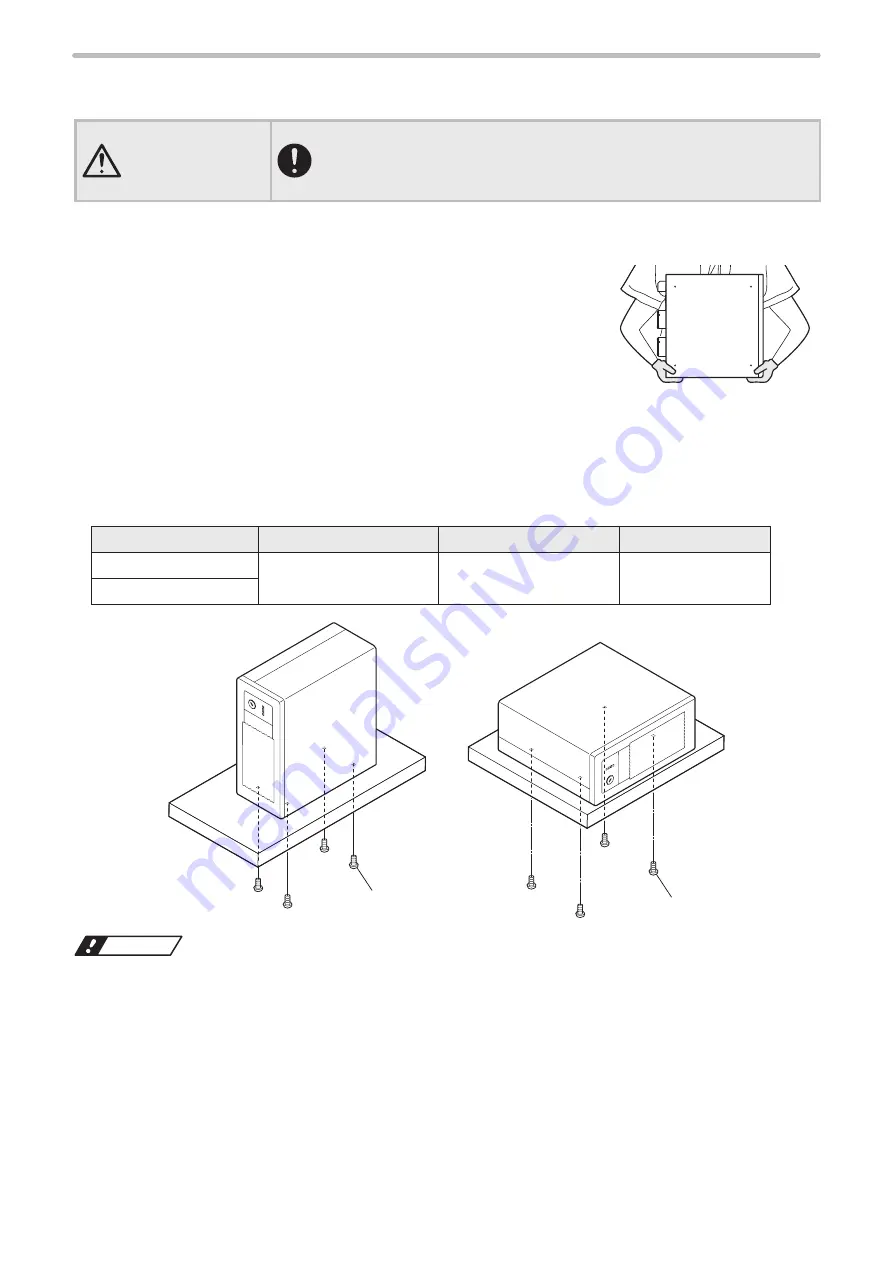
Carrying the controller
To carry the controller, hold the bottom of the unit with both hands.
Do not hold the cables or connectors at carrying this product.
Installation method
• The controller may be installed vertically or horizontally.
• For horizontal installation, ensure that the key switch side is at the bottom.
• For details of installation, refer to “1-5-2 Controller” (P.25).
• Fix the controller in the following conditions.
Fixing surface
Fixing screw
Screw insert length
Tightening torque
Bottom
M5 screws at 4 positions
6 mm or below
2.0 N·m or below
Side (front left side)
M5 screw
M5 screw
ワㄐㄕㄊㄆ
• Do not insert any screw of length exceeding the specification. Otherwise, the failure of the product may be caused.
• Do not install the laser marker at a place where vibrations and shocks can be directly transmitted to it. In any
environment where effects of vibration are concerned, take measures against vibration on the product, e.g. fitting rubber
feet.
ME-LPGS-SM-8
Summary of Contents for LP-GS Series
Page 17: ...1 Product Overview ME LPGS SM 8 ...
Page 32: ...2 Laser Marker Installation ME LPGS SM 8 ...
Page 48: ...3 Operation Method ME LPGS SM 8 ...
Page 68: ...4 External Control Using I O ME LPGS SM 8 ...
Page 107: ...5 External Control by Communication Commands ME LPGS SM 8 ...
Page 116: ...6 Link Control with External Devices ME LPGS SM 8 ...
Page 141: ...7 Maintenance ME LPGS SM 8 ...
Page 161: ...161 MEMO ME LPGS SM 8 ...
Page 162: ...Troubleshooting ME LPGS SM 8 ...
Page 186: ...Index ME LPGS SM 8 ...
Page 189: ......
Page 190: ... Panasonic Industrial Devices SUNX Co Ltd 2014 2019 April 2019 ...

