140
⿎
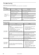
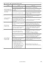
Lasing operation
Troubles
Causes
Measures
Marking cannot be done.
(The laser emission
indicator blinks but
marking is not performed
on the work piece.)
Obstacle hinders laser beam.
• Remove obstacle between laser emission port
of laser marker head and work piece.
• For LP-RF/LP-RV series, remove the
protection cap of the laser emission port.
Distance to work piece is not
appropriate.
Adjust distance between bottom surface of laser
marker head and the work piece surface as
specified.
For LP-GS series:
The set Z-position does not match the
height of the actual target object.
(The LP-GSxxx-L type is excluded.)
Set the Z-position according to the work piece
height.
The work piece is not in place.
• Check the marking position using the guide
laser or guide pointer to check if the work piece
is out of the specified position.
• For LP-RC/LP-RF/LP-RV series:
Connecting a sensor to TARGET DETECTION
IN (X7) of I/O terminal block, you can check
the presence of the work piece during laser
radiation.
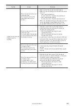
Laser power is insufficient.
• Increase laser power (including correction
factor).
• Decrease scan speed (including correction
factor).
Laser type (wavelength, output power,
etc.) is not appropriate for material of
the work piece.
Materials can be marked differ depending on
wavelength and output power of laser marker.
• LP-GS/LP-RC is not suitable for metal
material.
• LP-RF/LP-RV is not suitable for transparent
material.
Marking is not performed
in RUN/REMOTE mode.
(The laser emission
indicator does not light.)
In RUN mode:
The RUN Mode is not active or the
marking start signal is not input.
Turn the RUN mode ON, and then input a signal
to TRIGGER IN of the I/O terminal block.
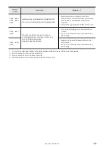
The marking trigger signal of the I/O
terminal block is not input.
Check connections with external equipment for
mis-connection, disconnection or contact failure
due to any loose connector.
Confirm that TRIGGER IN is input by one-shot
signal of more than 2ms per marking cycle.
The marking trigger is entered while
the marking ready is OFF.
Refer to “External Control” in Troubleshooting.
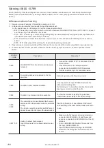
Sometimes laser is
emitted unintentionally.
Fumes causes malfunction of
photoelectric sensor for marking trigger
signal.
• Install a dust collector to eliminate the fume
(gas) generated during lasing.
• Check that dust collector works well.
ME-LP-GS-SR-COMP-3
Summary of Contents for LP-GS Series
Page 11: ...1 Preparation of Command Control ME LP GS SR COMP 3...
Page 26: ...2 Communication Control Basics ME LP GS SR COMP 3...
Page 50: ...3 Data Format for Each Command ME LP GS SR COMP 3...
Page 136: ...136 MEMO ME LP GS SR COMP 3...
Page 137: ...Troubleshooting ME LP GS SR COMP 3...
Page 163: ...Character Code Table ME LP GS SR COMP 3...
Page 176: ...Index ME LP GS SR COMP 3...
Page 178: ...178 W Warning 154 ME LP GS SR COMP 3...
Page 179: ......
Page 180: ...Panasonic Industrial Devices SUNX Co Ltd 2014 2019 April 2019...


