20 Function settings
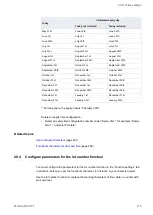
5. To add or edit the offset values, double-click on a table row.
6. In the “External offset” dialog, specify any of the following parameters.
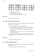
You can specify different parameters to correct the marking position.
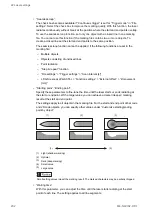
The following figure shows these parameters.
+Y
-Z
+X
-X
+Z
+
-
-Y
(1)
(2)
(3)
(5)
(4)
(1) X-movement
(2) Y-movement
(3) Z-movement
(4) Rotation (-)
(5) Rotation (+)
• “X-movement [mm]”, “Y-movement [mm]”:
Enter a value to move all marking data in the file along the x-axis and y-axis
• “Z-movement [mm]” (LP-GS except LP-GS051-L):
Enter a value to position all marking data in the file along the z-axis.
• “Rotation movement [°]”:
Specify an angle to rotate all marking data in the file. The rotation center is the
center of the marking field. Enter a positive value for counterclockwise rotation and a
negative value for clockwise rotation.
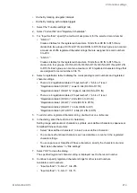
Correct the laser power:
• “Laser power correction [%]”:
To correct the laser power of all marking data in the file, enter a value in the text box.
The correction ratio is calculated based on the value set as 100% in “Laser settings”.
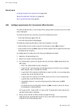
7. Select “OK” to close the dialog.
The specified offset values are displayed next to the record number.
8. Continue to specify offset values for other record numbers.
Available record numbers:
• “Input method” > “Lower 10 bits”: 0 to 1023
• “Input method” > “Lower 8 bits”: 0 to 255
• “Input method” > “Lower 4 bits”: 0 to 15
ME-NAVIS2-OP-1
221


