23 On-the-fly marking
2.
Go to the “Marking settings” screen and configure the layout of your marking data in
the marking image editor.
You do not have to set the position of the marking data at this moment. It will be
determined after you specify the on-the-fly marking settings.
3.
In the “Laser settings” tab, specify settings such as “Laser power” and “Scan speed
[mm/s]”.
Make sure that the marking time is short enough to perform the marking process
within the required cycle time.
4.
Select the “On-the-fly marking” tab and select “ON” for “On-the-fly marking”.
5.
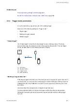
For “Moving direction”, specify the moving direction of the conveyor. Check the
direction of the laser head before you set the moving direction.
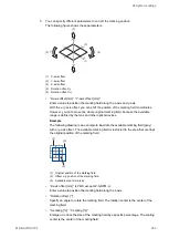
The icon in the marking image editor indicates the direction of the laser head.
6.
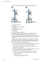
For “Trigger mode”, specify the mode of the marking trigger.
7.
Select a parameter for “Line speed control”.
If the line speed is fixed, select “Fixed speed”. If the line speed is fluctuating, set
“Encoder input” or “2 sensors input”. Use an external encoder or sensors to measure
the line speed.
If “Encoder input” or “2 sensors input” is set, the current line speed is calculated
based on the input signals from the encoder or the sensor. You can check the line
speed in “Monitor” > “On-the-fly”.
8.
Depending on the selected setting for “Line speed control”, set the following
parameters:
• If “Fixed speed” is set, specify a value for “Line speed [m/min]”.
• If “Encoder input” is set, specify a value for “Encoder resolution [pulses/mm]”.
• If “2 sensors input” is set, specify values for “Distance line speed sensors [mm]”
and “2 Sensors input time-out [s]”.
250
ME-NAVIS2-OP-1


