24 System settings
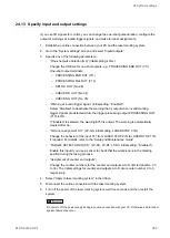
6. Turn off the power of the laser marking system, wait five seconds and then restart the
system.
Do not turn off the power supply during an online connection with your PC. Otherwise a data loss or
system failure may occur.
The new settings will be updated in the laser marking system.
Related topics
Establish an Ethernet connection between PC and laser marking system
24.15 Specify RS232C communication settings
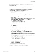
If you are using the RS232C interface, align the RS232C communication settings with the
external device.
• Use the RS232C interface to control the laser marking system by communication
commands or to connect a code reader.
• For details about the communication settings, refer to the “Serial Communication
Command Guide” of your laser marking system.
1. Establish an online connection between your PC and the laser marking system.
2. Go to the “System settings” screen and select “Communication”.
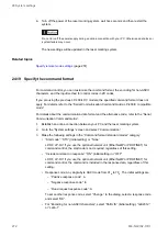
3. Specify the following RS232C communication settings:
• “RS-232C usage”:
Select “Communication commands” to control the laser marking system by
communication commands.
Select “Code reader” if you connect a code reader.
• “Baud rate [bit/s]”: Select the baud rate.
Initial setting: 9600
• “Data length [bit]”: 8 (fixed)
• “Parity”: “None” (initial setting), “Even” or “Odd”
• “Stop bits [bit]”: “1” (initial setting) or “2”
• “Check sum”: “OFF” (initial setting) or “ON”
The checksum is used to detect an error in data communication.
• “End code”: “CR” (initial setting) or “CR+LF”
The end code identifies the end of a message.
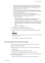
4. Select “Apply to laser marking system” in the ribbon.
5. Disconnect the online connection with the laser marking system.
ME-NAVIS2-OP-1
267


