184
Description
4
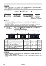
Work Distance (LP-SxxxW type only) :
Marking coordinates (X/Y) and marking field are corrected according to this setting when the work distance was
changed from the center position of work distance. Enter the value of work distance that is actually set.
Setting Range
173 to 213 mm (LP-S500W)*
Reference
•
The work distance setting is used to correct the marking position (X/Y) according to the setting distance. It does not
change the distance itself.
5
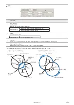
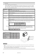
Line Width :
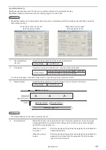
Specifies the interval between lines at the intersection point in a character when they are crossed.
If there is a space at the intersection point of the character or it is marked too deeply, adjust this value.
Setting Range
0.010 to 2.000 mm with the increment of 0.001 mm.
Baseline
width
Too large line width
Proper
Too small line width
Baseline
width
Baseline
width
Reference
•
This correction is invalid for some user-registration characters.
•
This correction is not effective for the logo data.
•
When requiring the thicken the actual marking width, set the line width for bold character at character condition. Refer
to “2-10-2 Character Conditions” (P.149).
•
The time for marking may be long if the setting value of the line width is smaller.
•
The initial value of the line width is set depending on the model as follows;
LP-M200/M500/MA00 : 0.06 mm
LP-S200/S500 : 0.06 mm
LP-Z130/Z250 : 0.07 mm
LP-M205/M505/MA05 : 0.08 mm
LP-S202/S502 : 0.04 mm
LP-Z256 : 0.14 mm
LP-MA06 : 0.1 mm
LP-S205/S505 : 0.1 mm
6
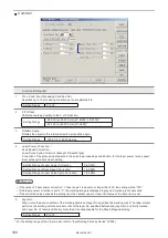
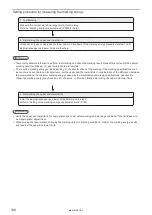
Marking Energy (LP-M series /LP-Sxxx type only) :
Measures the marking energy per trigger and sets the warning threshold of the marking energy.
For details of laser energy, refer to “2-11-2 Marking Energy Measurement” (P.187).
7
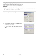
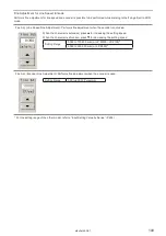
Marking Time Measurement :
Indicates the period of marking.
Press [MARKING TIME MEASUREMENT].
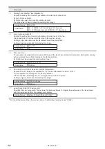
Reference
•
If a variable character such as counter is included in the character marked, the measurement of period is performed
with the current value.
•
In case the actual marking period is shorter than the one-shot output duration, the result of measurement is same as
the one-shot output time. Refer to “2-16-3 Communication, I/O Setting (Environment 3)” (P.232) for the detail of the one-
shot time setting.
• When performing marking to flying object with 3D setting, marking time cannot be measured regardless of using or
not using the encoder.
ME-LPMSZ-OP-7
Summary of Contents for LP-M Series
Page 11: ...1 Basic Operation Procedure ME LPMSZ OP 7 ...
Page 76: ...76 MEMO ME LPMSZ OP 7 ...
Page 77: ...2 Description of Operation Screen ME LPMSZ OP 7 ...
Page 102: ...102 Symbol ME LPMSZ OP 7 ...
Page 255: ...Troubleshooting ME LPMSZ OP 7 ...
Page 276: ...Appendix ME LPMSZ OP 7 ...
Page 304: ...Index ME LPMSZ OP 7 ...
Page 307: ...No 9000 0063 56V ...
Page 308: ... Panasonic Industrial Devices SUNX Co Ltd 2013 2019 March 2019 9000 0063 56V ...


