149
■
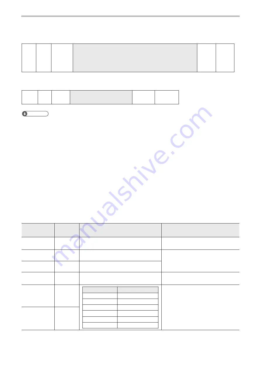
Character conditions: STC
Sets the condition for marking character string per line.
Setting / Readout data of character condition
STX
STC
Sub
command
[Character condition No.] [Start line] [End line] [Marking shape]
[Vary with the marking shape] [Font No.] [Bold line width]
[Laser power correction] [Scan speed correction]
[Laser pulse cycle correction]
Max. 73-byte (LP-F10 mode), 70-byte (LP-F10W mode)
(Check
sum)
Delimiter
Sub command is “S” at the time of setting and “A” for response data at the time of readout.
Readout request of character condition
STX
STC
R
[Character condition No.]
2-byte
(Check
sum)
Delimiter
Reference
•
The condition Nos. 31 and after cannot be set and read out. (NAK09 is returned.)
•
When the start line/end line is 31 to 99; font is 3 to 10, marking shape is proportional, arc radius and line width of bold
character; laser power correction, speed scan correction and laser pulse cycle correction are out of the setting range of
the LP-F10/LP-F10W, readout cannot be performed. (NAK15 is returned.)
• At the time of setting, the character height, character width and X coordinate are converted according to the definition of
the LP-M/LP-S/LP-Z series so that they have the same layout, and at the time of readout, they are converted according
to the definition of the LP-F10/LP-F10W. If any of the character height, character width and X coordinate exceeds the
setting range in this conversion, NAK09 is returned at the time of setting and NAK15 is returned at the time of readout.
• In readout response, the digit of 1 μm or 0.01° is rounded down. (Excluding the items with conversion process.)
•
When the marking shape is proportional, the kerning level should be set to level 2 that is supported by LP-F10/LP-F10W.
•
When the setting is performed using this command, the start point of the character string is set to the leftmost and the
layer No. is “0”.
•
Setting with this command in the LP-F10W mode, the laser pulse cycle correction is set to 100%.
•
For LP-SxxxW type, the laser pulse cycle correction setting does not affect the marking. Also this setting is not saved in
the file.
•
At marking of bold characters, set the values so ratio of character height to character width be within 1/10 to 10.
•
Set the Bold line width to 1/2 or less of the character height or the character width, whichever is smaller.
1. When markings from is straight line/proportional
Data length: 60-byte (LP-F10 mode), 57-byte (LP-F10W mode)
Name
Data length
[byte]
Description
Remarks
Character
condition No.
2
“01”–“30”
Start line
2
“01”–“30” [row]
The start and end line of character
string for marking with this condition is
indicated.
End line
2
“01”–“30” [row]
Marking shape
1
“0”: Straight line
“4”: Straight line proportional
Character
height
6
Model type*
Setting range [mm]
LP-Sxx0(W)
“000.20”–“090.00”
LP-Sxx5(W)
“000.20”–“160.00”
LP-Sxx2
“000.20”–“055.00”
LP-Mxx0/LP-Zxx0
“000.20”–“120.00”
LP-Mxx5
“000.20”–“220.00”
LP-Mxx6/LP-Zxx6
“000.20”–“330.00”
Character width
6
ME-LPMSZ-SR-9
Summary of Contents for LP-M Series
Page 8: ...1 Before External Control ME LPMSZ SR 9...
Page 16: ...2 Basics of Serial Communication RS 232 Ethernet ME LPMSZ SR 9...
Page 34: ...3 Communication Command and Function ME LPMSZ SR 9...
Page 165: ...Troubleshooting ME LPMSZ SR 9...
Page 186: ...Character Code Table ME LPMSZ SR 9...
Page 199: ...Index ME LPMSZ SR 9...
Page 202: ...202 MEMO No 9000 0063 59V ME LPMSZ SR 9...
Page 203: ...No 9000 0063 59V...
Page 204: ...Panasonic Industrial Devices SUNX Co Ltd 2013 2019 March 2019 9000 0063 59V...


