background image

58


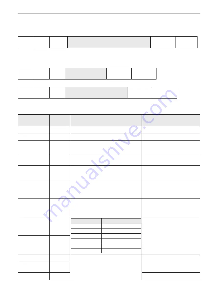
Bar code marking condition: BRF

Sets the marking condition for bar code and 2D code.

Setting / Readout data of bar code marking condition

STX

BRF

Sub 

command

[Bar code No.] [Layer No.] [Code


type]

[Setting data (varies depending on bar code type)]

(Check sum)

Delimiter

Sub command is “S” at the time of setting and “A” for response data at the time of readout.

Readout request of bar code marking condition

When the code type is other than composite:

STX

BRF

R

[Bar code No.]

2-byte

(Check sum)

Delimiter

When the code type is composite:

STX

BRF

R

[Bar code No.] [1D/2D selection]

3-byte

(Check sum)

Delimiter

In [1D/2D Selection] field, specify “1” for readout of 1D side or “2” for readout of 2D side of composite code.

1.  QR code (Data length: 44-byte)

Name

Data length 

[byte]

Description

Remarks

Bar code No.

2

“00”–“15”

Layer No.

2

“00”–“15”

Code type

2

“10”: Model 1

“11”: Model 2

“12”: Micro QR code

System 

reservation

1

“0” fixed

Version

2

Model 1: “00”–“14”

Model 2: “00”–“22”

Micro QR: “00”–“04”

When specifying “00”, it is 

automatically specified.

Data input mode

1

“0”: Number

“1”: Alpha (text)

“2”: Binary

“3”: Kanji

Error correction 

level

1

“0”: L

“1”: M

“2”: Q

“3”: H

For micro QR, Error Correction 

Level “H” cannot be used.

X position

8

Model type*

Setting range [mm]

LP-Sxx0(W)

“-045.000”–“+045.000”

LP-Sxx5(W)

“-080.000”–“+080.000”

LP-Sxx2

“-027.500”–“+027.500”

LP-Mxx0 / LP-Zxx0 “-060.000”–“+060.000”
LP-Mxx5

“-110.000”–“+110.000”

LP-Mxx6/LP-Zxx6

“-165.000”–“+165.000”

Specifies the center coordinate of 

the code.

Y position

8

Rotation angle

7

“-180.00”–“+180.00” [°]

Module H.

5

“0.001”–“9.999” [mm]

Interval of module in longitudinal 

direction.

Module W.

5

Interval of module in lateral direction

* For the detail of the model type, refer to “Target laser marker” (P.4).

ME-LPMSZ-SR-9

Summary of Contents for LP-M Series

Page 1: ...2019 3 panasonic net id pidsx global ME LPMSZ SR 9 No 9000 0063 59V Laser Marker Serial Communication Guide LP M series LP S series LP Z series...

Page 2: ...ay not infringe any intellectual property rights such as patent rights of a third party Trademark Windows is a registered trademark or trademark of Microsoft Corporation in the United States and or ot...

Page 3: ...ct the eyes against the scattered beam Never look at the direct beam or reflected beam even when you are wearing the protective goggles In order to prevent unexpected exposures from object to be marke...

Page 4: ...MA05 S LP MA05 S CHN LP MA05 LP MAxx LP MA06 LP MA06 CHN LP MA06 S LP MA06 S CHN LP MA06 LP MAxx LP Mxx6 LP S200 LP S200 CHN LP S200 SF LP S200 LP S2xx LP Sxx0 LP Sxxx LP Sxxx SF LP S Sries LP Sxxx W...

Page 5: ...e laser marker and set the marking data using touch panel console or monitor and mouse Laser Marker NAVI plus Operation Manual This manual describes how to operate the laser marker and set the marking...

Page 6: ...6 2 1 Preparation of Command Control 17 2 1 1 RS 232C 17 2 1 2 Ethernet 20 2 2 Command Reception Condition 22 2 3 Connection Check 23 2 4 Control Sample 24 2 5 Communication Data Format 28 2 5 1 Comma...

Page 7: ...7 Warning 181 Character Code Table 186 ASCII Code 187 Shift JIS Code 188 Index 199 Index 200 ME LPMSZ SR 9...

Page 8: ...1 Before External Control ME LPMSZ SR 9...

Page 9: ...minal block I O connector PLC etc External control by serial communication commands RS 232C Ethernet Remote mode operation Controls the laser marker from external devices such as PLC using communicati...

Page 10: ...o 1 2 Before External Control P 11 Turn ON key switch of laser marker controller The device is ready for receiving the marking starting signal trigger For LP Mxxx S type open the laser gate to turn ON...

Page 11: ...en Refer to 1 2 2 Communication condition setting P 14 Refer to 1 2 3 Shift to remote mode P 15 Remote mode ON Communication environment setting Turn ON laser marker DIP switch setting Control by seri...

Page 12: ...h No 2 select the control method I O or command for some specific operations DIP switch No 2 Control method for specific operations ON Control by serial communication commands for the following operat...

Page 13: ...vailable CAUTION If the DIP switch No 5 or No 6 are used while turned on construct a system for re pumping the laser manually as safety protection measures after the stop of the laser radiation due to...

Page 14: ...ounter end output signals in I O connector pin No 32 to 35 respectively 4 To use the serial communication commands set communication conditions for Ethernet or RS 232C For RS 232C Configure the commun...

Page 15: ...ON the remote mode input X5 of the I O terminal on the rear of the controller X5 REMOTE IN Turn ON the DIP switch No 5 Refer to 1 2 1 DIP switch setting P 12 Reference When DIP switch No 5 is ON the r...

Page 16: ...2 Basics of Serial Communication RS 232 Ethernet ME LPMSZ SR 9...

Page 17: ...uld be selected from either the serial communication or I O Turn the No 2 DIP switch on the back surface of controller before turning on the power to select the control serial communication or I O Tho...

Page 18: ...available RS 232C cable connect only 3 signals of RxD TxD and GND and do not use other signals on the laser marker side The external controller may need a signal line connection loop back line other...

Page 19: ...n Odd initial setting None Stop Bits 1 bit 2 bit initial setting 1 bit Flow control None Check sum OFF ON initial setting OFF Delimiter CR CR LF initial setting CR Start Code Setting request Reading r...

Page 20: ...55 255 255 1 Initial value Unspecified 0 0 0 0 Port 5001 to 65534 except 9090 and 9091 Initial value 9094 Start Code Setting request Reading request Reading response STX Normal response ACK Abnormal r...

Page 21: ...marker one to many through a HUB or a router Use a HUB or a router that supports 1000BASE T 100BASE TX 10BASE T and Category 5e or higher straight cables for connection HUB or router Straight cable Ex...

Page 22: ...ission MKM command The following commands can be transmitted while the shutter is opened There is no need to set reception mode ON for command reception permission MKM command File change specified wi...

Page 23: ...e table and add them all together Check sum is the value calculated by converting the lower two digits of the total value into two characters in the ASCII code 02 HEX 46 HEX 4E HEX 4F HEX 53 HEX 32 HE...

Page 24: ...SHT command 8 Status request STS command 10 Command reception mode ON MKM command 11 Various conditions setting LSR command 12 Command reception mode OFF MRK command 13 Shutter setting close SHT comma...

Page 25: ...Remote mode ON Remote mode OFF 2 Marking character string setting MCS command or STR command 3 Shutter setting open SHT command 4 Status request STS command 5 Marking trigger MRK command 6 Command re...

Page 26: ...S type open the laser gate to turn ON the ready signal Laser gate can be controlled with any timing regardless of the command sequence by the external signal input READY OFF 1 Laser pumping ON LSR co...

Page 27: ...file to be marked 1 Laser pumping ON LSR command Remote mode ON Remote mode OFF 2 File switching File No specified FNO command 3 Shutter setting open SHT command 4 Status request STS command 7 Shutte...

Page 28: ...R Readout of setting data Read Note S or R cannot be selected for some commands Data Data specified per command The content to be specified varies per command Refer to 3 Communication Command and Fun...

Page 29: ...Delimiter Two characters Single character Head End Code Description Start code ACK 06 HEX fixed A start code is a code to identify the data head and to indicate that the data is a response data for n...

Page 30: ...losed No setting of Serial data input on character string When SIN command is used No setting of Serial data on external offset condition When SEO command is used 12 The file cannot be saved due to la...

Page 31: ...varies per command Refer to 3 Communication Command and Function P 34 Check sum 1 Check sum indicates the lower 1 byte of adding result of value binary from the start code to the last data by converti...

Page 32: ...ication sequence of setting readout request data When the requested data was received normally from the external device the laser marker transmits response data for normal receiving to the setting req...

Page 33: ...d during marking operation Warning occurred according to the setting of marking condition during marking operation Shutter open command Shutter close command External device Communication sequence whe...

Page 34: ...3 Communication Command and Function ME LPMSZ SR 9...

Page 35: ...fied FNO Specifies the file No to change the file P 44 File change Comment specified FNN Specifies the file name comment to change the file P 44 File overwriting registration FOR Overwrite and registe...

Page 36: ...cified with 2 bytes alternate codes KANA KANJI and function characters P 57 Bar code marking condition BRF Sets the marking condition for bar code and 2D code P 58 Human readable text BRV Sets the mar...

Page 37: ...coordinates using I O input P 91 External offset coordinates OFS Sets offset coordinates used for External Offset Function to switch coordinates using I O input P 92 Step repeat condition SRC Sets the...

Page 38: ...tio in comparison with the default laser power P 107 Low power detect level LP M5xx LP M2xx LP Sxxx LP SxxxW only PWL Sets thresholds for determination of whether the result of the power measurement o...

Page 39: ...n command including an action to update the laser marker data To resume the ready ON status after command transmission set reception mode OFF Reference For details on command reception permission refe...

Page 40: ...arking ready status Trigger status 5 byte Check sum Delimiter Name Data length byte Description Remarks Error occurrence status 1 0 No error 1 Error occurrence Laser pumping status 1 0 Laser pumping O...

Page 41: ...ommand after marking status transmission permission is set STX MST A Status Marking energy measurement Marking energy value 14 byte LP Mxxx LP Sxxx 4 byte LP SxxxW LP Zxxx Check sum Delimiter Name Dat...

Page 42: ...operation is started when this command is accepted During equidistant status at marking to flying object the instruction of marking start stop is executed except LP SxxxW type Reference Marking is per...

Page 43: ...Dual Pointer it indicates Z displacement of guide display in comparison to the base work distance omissible For the detail of the model type refer to Target laser marker P 4 Reference Omit the Z offs...

Page 44: ...to the file name comment Change File No STX FNN S File name Max 20 byte Check sum Delimiter Name Data length byte Description Remarks File name Max 20 Specify the file name with 10 or less characters...

Page 45: ...NM Sub command File name Max 20 byte Check sum Delimiter Sub command is S at the time of setting and A for response data at the time of readout Readout request of file name STX FNM R Check sum Delimit...

Page 46: ...dout data includes characters that cannot be expressed in ASCII code such as Katakana and Kanji 2 byte character only these 2 byte characters are read out in shift JIS code In this case the maximum re...

Page 47: ...ot used in case of no offset Z counter numbering system 1 1 to 9 A to Z This letter is not used when decimal number is used 0N XnY Z with zero _N XnY Z right aligned without zero N_ XnY Z left aligned...

Page 48: ...with serial data input For resetting the data set the reception mode ON for command reception permission MKM command or close the shutter SIN command cannot be used with the rank function external of...

Page 49: ...ns approx 1 second after the shutter open input T2 0 ms or more After confirming the marking output is turned ON the next SIN command data can be sent Reference The command for serial data input SIN c...

Page 50: ...rking character string Max 21 byte Check sum Delimiter Sub command is S at the time of setting and A for response data at the time of readout Readout request of rank character string STX RKS R Data No...

Page 51: ...m Delimiter Name Data length byte Description Remarks Counter No 1 0 7 4 7 common counter Current value 6 000000 999999 No minus number Initial value 6 000000 999999 End value 6 000000 999999 Step 6 0...

Page 52: ...ecember 31 2099 Setting Readout data of expiry date time condition STX LMT Sub command Expiry No Expiry Reference unit Start date 7 byte Check sum Delimiter Sub command is S at the time of setting and...

Page 53: ...LTC R Lot No 1 byte Check sum Delimiter Name Data length byte Description Remarks Lot No 1 0 7 4 7 common lot Lot target 2 00 Current 01 08 expiry 1 to 8 10 17 counter 0 to 7 The unit of period to swi...

Page 54: ...ounter 01 60 The setting range varies depending on the condition of period unit Start period 6 Period condition Setting range Year Week based year 198000 209900 Month 000001 000012 Day 000001 000031 Y...

Page 55: ...ce When setting bar code marking data in multiple lines data in each line are jointed in the order of line numbers and they are coded as the data in one line No line break is inserted for each line Wh...

Page 56: ...No line break is inserted for each line When setting bar code marking data in multiple lines the total input data should be 255 characters or less If readout data includes function characters such as...

Page 57: ...ta in one line No line break is inserted for each line When setting bar code marking data in multiple lines make sure the sum of all barcode data is 255 characters or less If readout data includes fun...

Page 58: ...e Name Data length byte Description Remarks Bar code No 2 00 15 Layer No 2 00 15 Code type 2 10 Model 1 11 Model 2 12 Micro QR code System reservation 1 0 fixed Version 2 Model 1 00 14 Model 2 00 22 M...

Page 59: ...of module in X direction Specifying 00 for number of both row and column encodes with the minimum size square X position 8 Model type 2 Setting range mm LP Sxx0 W 045 000 045 000 LP Sxx5 W 080 000 080...

Page 60: ...000 LP Mxx6 LP Zxx6 001 000 330 000 Narrow element 5 0 050 1 000 mm Indicates the width of narrow element of bar and space Set the larger value than Line width in laser setting screen X position 8 Mod...

Page 61: ...30 000 Narrow element 5 0 050 1 000 mm Indicates the width of narrow element of bar and space Set the larger value than Line width in laser setting screen X position 8 Model type Setting range mm LP S...

Page 62: ...eight 7 Model type Setting range mm LP Sxx0 W 001 000 090 000 LP Sxx5 W 001 000 160 000 LP Sxx2 001 000 055 000 LP Mxx0 LP Zxx0 001 000 120 000 LP Mxx5 001 000 220 000 LP Mxx6 LP Zxx6 001 000 330 000...

Page 63: ...x0 W 001 000 090 000 LP Sxx5 W 001 000 160 000 LP Sxx2 001 000 055 000 LP Mxx0 LP Zxx0 001 000 120 000 LP Mxx5 001 000 220 000 LP Mxx6 LP Zxx6 001 000 330 000 Separator height W 4 00 0 10 0 Specifies...

Page 64: ...LP Mxx6 LP Zxx6 001 000 330 000 Separator height W 4 00 0 10 0 Specifies the ratio to the module width of 1D side Symbol char in row 2 02 20 Only even value applied Module width 5 0 050 1 000 mm X pos...

Page 65: ...nded CC B 55 GS1 DataBar Expanded Stacked CC B 56 EAN UPC CC B 1 57 UCC EAN128 CC B Composite CC C 67 UCC EAN128 CC C Human readable text for 2D code 1 2 Invalid 3 Valid Composite row height 5 0 050 9...

Page 66: ...check digit UPC E 2 The number of column of bar code is limited according to bar code s type Bar code type The number of column available for CC A code The number of column available for CC B code UP...

Page 67: ...e of Composite code 2 2D side of Composite code When the code type is other than the Composite code select 1 X position 8 Model type Setting range mm LP Sxx0 W 045 000 045 000 LP Sxx5 W 080 000 080 00...

Page 68: ...a new line on 2D side Specifies the line interval at marking human readable text on a new line For the detail of the model type refer to Target laser marker P 4 2 When the barcode type is EAN UPC inc...

Page 69: ...er Sub command is S at the time of setting and A for response data at the time of readout Readout request data STX BCC R Check sum Delimiter Name Data length byte Description Remarks Bar code marking...

Page 70: ...ode 0 Margin 1 Dark Module 2 Light Module 3 Alignment 4 Finder Data Matrix code 0 Quiet Zone 1 Mark Module 2 Space Module 3 Border Character code 4 0000 2230 2239 or 8121 8152 Specifies the character...

Page 71: ...nded The logo file name corresponding to the specified number is indicated The logo file setting will be deleted when no file name is specified in this command For VEC file the extension can be omitte...

Page 72: ...limiter Name Data length byte Content Remarks Logo No 2 00 99 Layer No 2 00 15 X scale 8 0010 000 1000 000 Y scale 8 X position 8 330 000 330 000 mm Specifies the origin coordinate of the logo Y posit...

Page 73: ...s the origin coordinate of the logo Y position 8 Rotation angle 7 180 00 180 00 Size specification 1 0 Height Width 1 Width 2 Height width fixed 3 As original graphic size Width 7 Model type Setting r...

Page 74: ...Sxx0 W 045 000 045 000 LP Sxx5 W 080 000 080 000 LP Sxx2 027 500 027 500 LP Mxx0 LP Zxx0 060 000 060 000 LP Mxx5 110 000 110 000 LP Mxx6 LP Zxx6 165 000 165 000 Y coordinate of start point 8 X coordin...

Page 75: ...d part 7 Model type Setting range mm LP Sxx0 W 000 010 090 000 LP Sxx5 W 000 010 160 000 LP Sxx2 000 010 055 000 LP Mxx0 LP Zxx0 000 010 120 000 LP Mxx5 000 010 220 000 LP Mxx6 LP Zxx6 000 010 330 000...

Page 76: ...l type Setting range mm LP Sxx0 W 000 010 090 000 LP Sxx5 W 000 010 160 000 LP Sxx2 000 010 055 000 LP Mxx0 LP Zxx0 000 010 120 000 LP Mxx5 000 010 220 000 LP Mxx6 LP Zxx6 000 010 330 000 Set the larg...

Page 77: ...LAY R Processing condition No 2 byte Check sum Delimiter Name Data length byte Description Remarks Processing condition No 2 00 15 Layer No 2 00 15 X offset 8 Model type Setting range mm LP Sxx0 W 04...

Page 78: ...miter Readout data of arbitrary point radiation coordinate and time STX PRD A Point radiation condition No Line No Radiation time Laser power correction X position Y position Max 31 byte Check sum Del...

Page 79: ...sing condition STX PRF R Point radiation condition No 2 byte Check sum Delimiter Name Data length byte Description Remarks Point radiation condition No 2 00 15 Layer No 2 00 Fixed value X offset 8 Mod...

Page 80: ...025 000 025 000 LP Sxxx LP SxxxW As this item is not available for the LP S series set to 000 000 LP Mxxx LP Zxxx The marking position is offset to the Z direction Rotation offset 7 180 00 180 00 Over...

Page 81: ...er condition No 2 01 99 X position 8 When the marking form is other than sector marking Model type Setting range mm LP Sxx0 W 045 000 045 000 LP Sxx5 W 080 000 080 000 LP Sxx2 027 500 027 500 LP Mxx0...

Page 82: ...emarks Character condition No 2 01 99 Layer No 2 00 15 Start line 2 01 99 row The start and end line of character string for marking with this condition is indicated End line 2 01 99 row Marking shape...

Page 83: ...P Zxx0 0 000 2 000 LP Sxx5 W LP Mxx5 LP Mxx6 LP Zxx6 0 000 4 000 Laser power correction 3 000 999 The correction ratio is calculated using the value set at the laser condition as 100 With LP SxxxW typ...

Page 84: ...haracter interval 7 180 00 180 00 The angle between the center of character and the center of next character is indicated Font No 2 Char Font 01 10 The number corresponding to the 10 fonts previously...

Page 85: ...marking pitch for the bold character is indicated Kerning 1 1 Level 1 Minimize the base point of the character interval with this condition The letter spacing of the letter i and l small letter L are...

Page 86: ...ter coordinate of 3D work is indicated Center position Y 8 Center position Z 8 Rotation angle X 7 090 00 090 00 Rotation angle Y 7 090 00 090 00 Rotation angle Z 7 180 00 180 00 Height 7 Model type Se...

Page 87: ...01 000 220 000 LP Mxx6 LP Zxx6 001 000 330 000 Vertical cone length lateral or height vertical is indicated Diameter 1 7 The diameter of the top end side direction of vertical cone is indicated Diamet...

Page 88: ...90 00 090 00 Rotation angle Y 7 090 00 090 00 Rotation angle Z 7 180 00 180 00 Diameter 7 Model type Setting range mm LP Mxx0 LP Zxx0 001 000 120 000 LP Mxx5 001 000 220 000 LP Mxx6 LP Zxx6 001 000 33...

Page 89: ...For the detail of the model type refer to Target laser marker P 4 Reference The command for serial offset input is enable when serial offset is set with external offset condition Transmission is avai...

Page 90: ...T2 0 ms or more After confirming the marking output is turned ON the next SEO command data can be sent Reference Transmission is available for the command for serial offset SEO only during remote con...

Page 91: ...ting Readout data of external offset condition STX OFC Sub command External offset 1 byte Check sum Delimiter Readout request of external offset condition STX OFC R Check sum Delimiter Name Data lengt...

Page 92: ...00 1023 The parallel data number in which offset is set is indicated X offset 8 Model type Setting range mm LP Sxx0 W 045 000 045 000 LP Sxx5 W 080 000 080 000 LP Sxx2 027 500 027 500 LP Mxx0 LP Zxx0...

Page 93: ...000 220 000 LP Mxx6 LP Zxx6 000 000 330 000 The marking pitch to the Y direction is specified Column step 7 The marking pitch to the X direction is specified X offset 8 Model type Setting range mm LP...

Page 94: ...e as fine adjustment type data length max 45 byte Name Data length byte Description Remarks List line 4 0000 0399 Fine adj type 1 1 Single fine adjustment Target row 3 001 400 Target column 3 001 400...

Page 95: ...stment In case of fine adjustment for all columns rows the specified column row and all subsequent columns rows will be subject to fine adjustment Fine tune X 8 Model type 1 Setting range mm LP Sxx0 W...

Page 96: ...the layer No from 0 to 15 send 0 mark off or 1 mark on for every 16 layers Even not all layers are used send 16 digits with 0 or 1 Data example Setting for marking off to the layer No 2 and 3 and no d...

Page 97: ...t of 0 5 For the detail of the model type refer to Target laser marker P 4 Scan speed SSP Sets the scan speed of the laser Setting Readout data of scan speed STX SSP Sub command Scan speed 5 byte Chec...

Page 98: ...k sum Delimiter Name Data length byte Description Remarks Laser pulse cycle 4 Model type Setting range s LP S5xx LP M5xx 02 0 20 0 LP S2xx LP M2xx 02 0 50 0 LP MAxx 05 0 10 0 LP Z130 10 0 50 0 LP Z250...

Page 99: ...Mxxx LP Zxxx To keep a uniform diameter of the laser spot within the marking field specify this mode The spot size is adjusted to the selected plane The laser spot will have the same diameter in the a...

Page 100: ...timing of starting laser is adjusted Adjustment of ending point 4 100 100 The timing of stopping laser is adjusted Edge adjustment 3 000 100 The wait at edge is adjusted Curve adjustment 3 000 100 Th...

Page 101: ...ction Encoder Trigger type 3 byte Check sum Delimiter Sub command is S at the time of setting and A for response data at the time of readout Readout request of trigger condition STX TRG R Check sum De...

Page 102: ...of delay STX DLY R Check sum Delimiter Name Data length byte Description Remarks Delay time distance 6 Delay Time 000000 005000 ms Delay Distance 000 00 500 00 mm When the moving speed is still delay...

Page 103: ...mm Available only when the moving direction is other than still and trigger type is equidistant Flying object wait MWT Supported models LP Mxxx LP Sxxx LP Zxxx Sets the waiting time for marking corre...

Page 104: ...ses is indicated available only when the traveling direction is other than still and encoder signal is OFF For the detail of the model type refer to Target laser marker P 4 Encoder signal ENC Supporte...

Page 105: ...onse data for abnormal receiving NAK03 or NAK99 is returned when the laser pumping is OFF or the shutter is opened Even when the reception mode ON is set for the command reception permission MKM comma...

Page 106: ...Indicates initial ratio Determination 1 0 Correct When laser power setting value is not 100 0 and after the power correction this data is always 0 1 Lower than the low power detect Indicates whether...

Page 107: ...ction Reference The power check command is rejected when the DIP switch No 2 in the rear side of the laser marker is set to OFF Transmit the power check command with laser pumping turned ON and the sh...

Page 108: ...correction ratio 5 050 0 200 0 When the power correction has not been performed this value is 000 Correction date 14 For 15 00 00 on April 1 2012 20120401150000 When the power correction has not been...

Page 109: ...plays the measurement results of marking energy mJ and time on the setting screen when Test marking is finished Setting Readout data the marking energy indicating STX MEM Sub command Marking energy in...

Page 110: ...ower limit 18 byte Check sum Delimiter Sub command is S at the time of setting and A for response data at the time of readout Readout request out marking energy upper lower limits STX MEN R Check sum...

Page 111: ...the counter value is not changed even when a counter is set This command is not acceptable when the No 2 DIP switch on the back surface of controller is turned to OFF This command can be transmitted w...

Page 112: ...en the laser pumping is completed and the shutter is closed or the command reception mode ON is set by Command reception permission MKM command The laser is radiated at the center position The laser p...

Page 113: ...se to error code readout STX ECR A Error code Error type 5 byte Check sum Delimiter Name Data length byte Content Remarks Error code 4 0000 No error E001 E999 Error codes Error type 1 0 No error 1 Ala...

Page 114: ...year 4 1980 2037 year Month 2 01 12 month Day 2 01 31 day Hour 2 00 23 hour Minute 2 00 59 minute Second 2 00 59 second Reference The setting changed by this command is saved without overwriting Era y...

Page 115: ...sday Reference The setting changed by this command is saved without overwriting I O environment ENV Sets the operating environment of the input output terminal Setting Readout data of I O environment...

Page 116: ...nce P 32 Make sure that the command format used for the older laser marker LP F10 F10W is the same as that of LP M LP S LP Z series specified in 2 5 Communication Data Format P 28 It is not allowed to...

Page 117: ...such as ready status and error occurrence status P 123 Marking status transmission permission MST Enables automatic response of marking result e g normal end and error occurrence etc at the end of ma...

Page 118: ...R code module marking pattern P 142 Data Matrix code data Shift JIS code specified DMS Sets character string to be encoded as a Data Matrix code by shift JIS code P 143 Data Matrix code marking condit...

Page 119: ...f flying object P 160 Delay DLY Sets the delay time and distance from trigger input to marking startup P 161 Marking interval INT Sets the marking interval distance in Equidistant Marking setting for...

Page 120: ...command Command mode 1 byte Check sum Delimiter Sub command is S at the time of setting and A for response data at the time of readout Readout request of command mode STX RSM R Check sum Delimiter Na...

Page 121: ...e Marking mode 1 0 Reception mode ON Start command reception in the marking ready OFF status 1 Reception mode OFF Finish command reception and resume the marking ready ON status In the shutter open or...

Page 122: ...takes about 20 seconds for LP Mxxx LP Sxxx LP Zxxx type and about 15 seconds for LP SxxxW type from turning ON the laser pumping to completion of pumping Shutter SHT Controls the internal shutter open...

Page 123: ...hutter close or command reception mode ON including while the shutter is opened 1 Marking being operated Shutter open except when the command reception mode is ON Shutter and command reception mode MK...

Page 124: ...failure occurs when marking is normally completed or when character string is set outside the marking area transmission permission when receiving a marking trigger from the RS 232C after marking stat...

Page 125: ...arking operation is started when this command is accepted During equidistant status at marking to flying object the instruction of marking start stop is executed except LP SxxxW type Reference Marking...

Page 126: ...ence The file Nos 256 and after cannot be specified NAK09 is returned NAK15 is returned when the readout was performed with the file No 256 to 2047 When new file is created using the communication com...

Page 127: ...file name STX FNM Sub command File name Max 20 byte Check sum Delimiter Sub command is S at the time of setting and A for response data at the time of readout Readout request of file name STX FNM R C...

Page 128: ...marks Line No 2 01 30 row Marking character string Max 30 Characters within the range from 20 HEX to 7E HEX of ASCII code functional characters should not be included Specify 0 byte to the character s...

Page 129: ...ommand is S at the time of setting and A for response data at the time of readout Readout request of marking character string STX STR R Line No 2 byte Check sum Delimiter Name Data length byte Descrip...

Page 130: ...function number 0 to 3 date time number 0 current date time 1 to 4 expiry date time rank function number 0 to 3 serial data function number 0 to 9 A to F bar code number 0 to 3 Y counter offset 1 to...

Page 131: ...r command reception permission MKM command the serial data can be transmitted to the laser marker For using this command set serial data of function characters at setting screen beforehand When using...

Page 132: ...ut Setting Readout data of rank character string STX RKS Sub command Data No Marking character string Max 21 byte Check sum Delimiter Sub command is S at the time of setting and A for response data at...

Page 133: ...No minus number Initial value 6 000000 999999 End value 6 000000 999999 Step 6 000000 999999 Count source 1 0 Counter 0 1 Counter 1 2 Counter 2 3 Counter 3 4 Trigger input Reference The common counte...

Page 134: ...f readout Readout request of expiry date time condition STX LMT R Expiry No 1 byte Check sum Delimiter Name Data length byte Description Remarks Expiry No 1 1 4 Expiry 3 001 999 Reference unit 1 Expir...

Page 135: ...3 Lot target 1 0 Current 1 Expiry 1 2 Expiry 2 3 Expiry 3 4 Expiry 4 The unit of period to switch the character string for marking is indicated Period unit 1 0 Year 1 Month 2 Day 3 Y M 4 M D 5 Day of...

Page 136: ...the condition of period unit Start period 6 Period condition Setting range Year 198000 209900 Month 000001 000012 Day 000001 000031 Y M 198001 209912 M D 000101 001231 The higher 4 characters month t...

Page 137: ...me Data length byte Description Remarks Bar code No 1 0 3 Bar code data Max 60 For the method to specify the bar code data refer to Setting method of character string for marking specified with shift...

Page 138: ...9 1 ITF Inversion 1 0 Do not invert 1 Invert Check character 1 0 Absence 1 Presence Bar code height 6 Model type Setting range mm LP Sxx0 W 001 00 090 00 LP Sxx5 W 001 00 160 00 LP Sxx2 001 00 055 00...

Page 139: ...P 4 Reference The bar code No 4 to 7 cannot be set and read out NAK09 is returned Readout is available only when CODE39 ITF is set in the bar code type When other bar code is set NAK15 is returned In...

Page 140: ...thod of character string for marking specified with shift JIS code P 130 for the detail of the setting method of QR Code Data Specifies the character setting in the specified line In case of QR code m...

Page 141: ...be used X position 7 Model type Setting range mm LP Sxx0 W 045 00 045 00 LP Sxx5 W 080 00 080 00 LP Sxx2 027 50 027 50 LP Mxx0 LP Zxx0 060 00 060 00 LP Mxx5 110 00 110 00 LP Mxx6 LP Zxx6 165 00 165 0...

Page 142: ...e Laser Pulse Cycle Correction 3 byte Finder pattern 13 Same as above Specifies the finder pattern When 0000 is specified for the character code marking is performed at the pattern setting of dark mod...

Page 143: ...60 Refer to Setting method of character string for marking specified with shift JIS code P 130 for the detail of the setting method of Data Matrix data Specifies the character setting in the specified...

Page 144: ...of number of row and column is limited 1 Lateral symbol size the number of modules of the Data Matrix code X position 7 Model type 2 Setting range mm LP Sxx0 W 045 00 045 00 LP Sxx5 W 080 00 080 00 L...

Page 145: ...to use for the quiet zone pattern 000 200 050 200 050 200 Specify 100 in LP F10W mode Specifies a correction value of laser and scan speed when marking the quiet zone pattern Laser Power Correction 3...

Page 146: ...tension The CAD file specification will be deleted unless the file name is specified Reference Logo file for the LP F series is treated as one for LP F10 F10W marking area 90 mm x 90 mm Logo file used...

Page 147: ...rection ratio is calculated using the value set at the laser condition as 100 Laser Pulse Cycle Correction can be specified only in LP F10 mode Scan speed correction 3 050 200 Laser pulse cycle correc...

Page 148: ...axis Step repeat 1 0 OFF 1 ON Marking the same data is repeated to the X or Y axis direction Number of row 3 001 100 row number of row x column 900 The number of row to be marked to the Y direction i...

Page 149: ...the setting range in this conversion NAK09 is returned at the time of setting and NAK15 is returned at the time of readout In readout response the digit of 1 m or 0 01 is rounded down Excluding the i...

Page 150: ...old line width 5 LP F10 Mode 00 00 01 92 mm LP F10W Mode Model type Setting range mm LP Sxx0 W LP Sxx2 LP Mxx0 LP Zxx0 00 00 02 00 LP Sxx5 W LP Mxx5 LP Mxx6 LP Zxx6 00 00 03 20 Laser power correction...

Page 151: ...when the character string is marked over two or more lines Tilt angle 6 180 0 180 0 mm The tilt angle for character for marking to X axis is indicated When the tilt angle is set to 0 degree this item...

Page 152: ...r position of marking position to the next line is indicated when the character string is marked over two or more lines Start angle 6 180 0 180 0 The angle from the positive side of X coordinate with...

Page 153: ...coordinates of Offset function to switch coordinates using I O input Setting Readout data of external offset coordinates STX OFS Sub command Parallel data No X offset Y offset offset 21 byte Check sum...

Page 154: ...ription Remarks List line 2 00 99 Fine adj type 1 0 Setting deletion 2 In case of Single as fine adjustment type data length 21 byte Name Data length byte Description Remarks List line 2 00 99 Fine ad...

Page 155: ...ustment for all columns rows the specified column row and all subsequent columns rows will be subject to fine adjustment Fine tune X 6 Model type Setting range mm LP Sxx0 W 45 00 45 00 LP Sxx5 W 80 00...

Page 156: ...eries so that it is necessary to make some adjustments before the LP S series is used at first Scan speed SSP Sets the scan speed of the laser Setting Readout data of scan speed STX SSP Sub command Sc...

Page 157: ...0 40 0 For the detail of the model type refer to Target laser marker P 4 Reference Note that the setting range is different from the LP F series due to the difference of specification for the laser o...

Page 158: ...ne width for crossing avoidance at the crossing point of marking line is indicated Marking pitch 4 0 00 2 00 mm Sets the density at bold characters and bar codes Reference The bar code marking pitch a...

Page 159: ...200 The timing of stopping laser is adjusted Edge adjustment 3 000 200 The wait at edge is adjusted Curve adjustment 3 000 200 The wait at curved line is adjusted Reference In adjustment of starting e...

Page 160: ...and A for response data at the time of readout Readout request of trigger condition STX TRG R Check sum Delimiter Name Data length byte Description Remarks Moving direction 1 0 Still 1 Left 2 Right 3...

Page 161: ...than still delay distance is shown and the distance where the marking starts after the trigger input is displayed Marking interval INT Supported models LP Mxxx LP Sxxx LP Zxxx Sets the marking interva...

Page 162: ...nal is OFF Reference The value more than 60 000 cannot be specified NAK09 is returned When the setting exceeds 60 000 and readout is tried NAK15 is returned Encoder signal ENC Supported models LP Mxxx...

Page 163: ...s completed and the shutter is closed or the command reception mode ON is set by Command reception permission MKM command The laser is radiated at the center position The laser power can be changed by...

Page 164: ...ment ENV Sets the operating environment of the input output terminal Setting Readout data of I O environment STX ENV Sub command One shot output time Detect TRIG warning during marking 4 byte Check su...

Page 165: ...Troubleshooting ME LPMSZ SR 9...

Page 166: ...Restore the original condition of the safety equipment connected to the interlock connector Laser stop 2 on input terminal is in OPEN status or safety equipment such as door and switch connected to th...

Page 167: ...ows nothing Monitor is not turned on Check power to monitor Monitor cable is not connected Check that monitor cable is securely connected to connector VGA OUT on back of controller VGA compatible moni...

Page 168: ...Object is not in place Correct position of object Guide indication feature may be helpful for this purpose The laser marker is set for the marking on flying objects despite the static object Set Movi...

Page 169: ...ets write conditions For Trigger Marking Check if one shot signal of 10 ms or longer is provided per marking cycle For Equidistant Marking Check if status of the signal remains on during marking When...

Page 170: ...o that bottom surface of laser marker head and target surface of object are parallel with each other For LP M LP Z series Setting of Uniform Spot Mode is not appropriate Set the Uniform Spot mode with...

Page 171: ...are continuous vibrations coming from surrounding equipment such as motor and press Perform vibration prevention measures There are irregular vibrations coming from surrounding equipment such as air...

Page 172: ...o meandering motion of conveyor Secure objects to prevent misalignment Marking character pitch is unstable The line speed at the marking position is different from the speed at the installation site o...

Page 173: ...nd B phases Number encoder pulses Number of pulses mm x 4 Either A or B phase signal is refused A and B phase used Check that signal is applied to A and B phase terminals of encoder Measured number of...

Page 174: ...switched The port selected in the environment setting screen indicates the valid communication port RS 232C is selected at factory shipment The RS 232C cable is connected to the wrong connector RETURN...

Page 175: ...utter command SHT To change the DIP setting the switch of the laser marker should be set at power OFF state LP Mxxx S type Since the returning to the original position of the laser gate is not perform...

Page 176: ...on permission MKM command File Change No Specified FNO File Change Comment Specified FNN Shutter Control SHT Command Reception Permission MKM Laser Control LSR Counter Reset CTR Status Request STS Mar...

Page 177: ...toelectric sensor for marking trigger signal Install dust collector Check that dust collector works well Date is reset Internal battery has run out Contact failure may also be a cause of this symptom...

Page 178: ...description Measures E002 Emergency stop button of controller is pushed Except for LS1 models Release emergency stop button of controller by turning it in arrow direction E004 Laser Stop 2 of the inpu...

Page 179: ...has reached its limit Check that the ambient temperature is in the specified operating temperature Make sure cooling fan operates When not recovered contact our sales office E250 3 Detected a decreas...

Page 180: ...to lase as laser pumping is turned OFF Confirm that the laser pumping remains on during lasing operation Check wiring and control procedure for the I O terminal block wiring to communication port and...

Page 181: ...ened The laser gate is not opened when the test marking laser check radiation or laser power measurement is started Input the laser gate control signals for the returning to the original position afte...

Page 182: ...mory Marking data is too large The line length is too long spiral etc Reduce numbers of characters and logo data Reduce numbers of step repeat Reduce numbers of a start point and a end point of charac...

Page 183: ...or R14 format Delete the entities which are not supported by laser marker in the DXF file E670 1 Existed 3D marking data outside of marking area Adjust the setting of 3D work with overall layer condi...

Page 184: ...E700 Unable to lase as laser pumping is turned OFF Turn ON the laser pumping and after the laser pumping has completed start marking E701 Started laser power check in laser pumping OFF state Turn ON t...

Page 185: ...t Correct the Separator Height W or One Bar Code H settings so that the height is larger than the Line Width in the laser settings If you want to remove the separator set 0 to the Separator Height W E...

Page 186: ...Character Code Table ME LPMSZ SR 9...

Page 187: ...iter To input the control codes in the barcode 2D code strings set the code data as follows The following control codes EOT FS GS RS or US you can set with BBS or SIN command by using ASCII code In th...

Page 188: ...not registered into the blank The following symbols are registered in white Shift JIS JIS Symbols 8179 215A 817A 215B 819A 217A 819C 217C 819F 2221 81A1 2223 81A3 2225 81A5 2227 81AC 222E User defined...

Page 189: ...0 8380 2560 8390 2570 Greek characters 839E 2620 83AE 2630 83BE 2640 83CE 2650 Russian characters 843F 2720 844F 2730 845F 2740 846F 2750 8480 2760 8490 2770 889E 3020 88AE 3030 88BE 3040 88CE 3050 88...

Page 190: ...BE 3640 8BCE 3650 8BDE 3660 8BEE 3670 8C3F 3720 8C4F 3730 8C5F 3740 8C6F 3750 8C80 3760 8C90 3770 8C9E 3820 8CAE 3830 8CBE 3840 8CCE 3850 8CDE 3860 8CEE 3870 8D3F 3920 8D4F 3930 8D5E 3940 8D6F 3950 8D...

Page 191: ...DE 3E60 8FEE 3E70 903F 3F20 904F 3F30 905F 3F40 906F 3F50 9080 3F60 9090 3F70 909E 4020 90AE 4030 90BE 4040 90CE 4050 90DE 4060 90EE 4070 913F 4120 914F 4130 915F 4140 916F 4150 9180 4160 9190 4170 91...

Page 192: ...3F 4720 944F 4730 945F 4740 946F 4750 9480 4760 9490 4770 949E 4820 94AE 4830 94BE 4840 94CE 4850 94DE 4860 94EE 4870 953F 4920 954F 4930 955F 4940 956F 4950 9580 4960 9590 4970 959E 4A20 95AE 4A30 95...

Page 193: ...ft JIS JIS 0 1 2 3 4 5 6 7 8 9 A B C D E F 974F 4D30 975F 4D40 976F 4D50 9780 4D60 9790 4D70 979E 4E20 97AE 4E30 97BE 4E40 97CE 4E50 97DE 4E60 97EE 4E70 983F 4F20 984F 4F30 985F 4F40 986F 4F50 ME LPMS...

Page 194: ...996F 5150 9980 5160 9990 5170 999E 5220 99AE 5230 99BE 5240 99CE 5250 99DE 5260 99EE 5270 9A3F 5320 9A4F 5330 9A5F 5340 9A6F 5350 9A80 5360 9A90 5370 9A9E 5420 9AAE 5430 9ABE 5440 9ACE 5450 9ADE 5460...

Page 195: ...9E 5A20 9DAE 5A30 9DBE 5A40 9DCE 5A50 9DDE 5A60 9DEE 5A70 9E3F 5B20 9E4F 5B30 9E5F 5B40 9E6F 5B50 9E80 5B60 9E90 5B70 9E9E 5C20 9EAE 5C30 9EBE 5C40 9ECE 5C50 9EDE 5C60 9EEE 5C70 9F3F 5D20 9F4F 5D30 9F...

Page 196: ...BE 6240 E1CE 6250 E1DE 6260 E1EE 6270 E23F 6320 E24F 6330 E25F 6340 E26F 6350 E280 6360 E290 6370 E29E 6420 E2AE 6430 E2BE 6440 E2CE 6450 E2DE 6460 E2EE 6470 E33F 6520 E34F 6530 E35F 6540 E36F 6550 E3...

Page 197: ...DE 6A60 E5EE 6A70 E63F 6B20 E64F 6B30 E65F 6B40 E66F 6B50 E680 6B60 E690 6B70 E69E 6C20 E6AE 6C30 E6BE 6C40 E6CE 6C50 E6DE 6C60 E6EE 6C70 E73F 6D20 E74F 6D30 E75F 6D40 E76F 6D50 E780 6D60 E790 6D70 E7...

Page 198: ...7 8 9 A B C D E F E8EE 7070 E93F 7120 E94F 7130 E95F 7140 E96F 7150 E980 7160 E990 7170 E99E 7220 E9AE 7230 E9BE 7240 E9CE 7250 E9DE 7260 E9EE 7270 EA3F 7320 EA4F 7330 EA5F 7340 EA6F 7350 EA80 7360 EA...

Page 199: ...Index ME LPMSZ SR 9...

Page 200: ...egistration 45 127 Flying Object Wait 103 Functional character 47 Functions for Safety Measures 23 G Guide LD Display 43 H Human Readable Text Setting 67 I I O Environment 115 164 J JIS level 1 189 JI...

Page 201: ...Shift JIS 47 130 Shift JIS Code 188 Shift to Remote Mode 15 Shutter 40 122 Status Request 40 123 Step Repeat Condition 93 Step Repeat Fine Adjustment 94 154 T Test Marking 111 Trademark 2 Trigger Cond...

Page 202: ...202 MEMO No 9000 0063 59V ME LPMSZ SR 9...

Page 203: ...No 9000 0063 59V...

Page 204: ...Panasonic Industrial Devices SUNX Co Ltd 2013 2019 March 2019 9000 0063 59V...

Reviews: