126
3-9-2 Ethernet
Port specifications
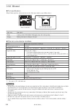
When Ethernet perform communication control of the laser marker, use an Ethernet port.
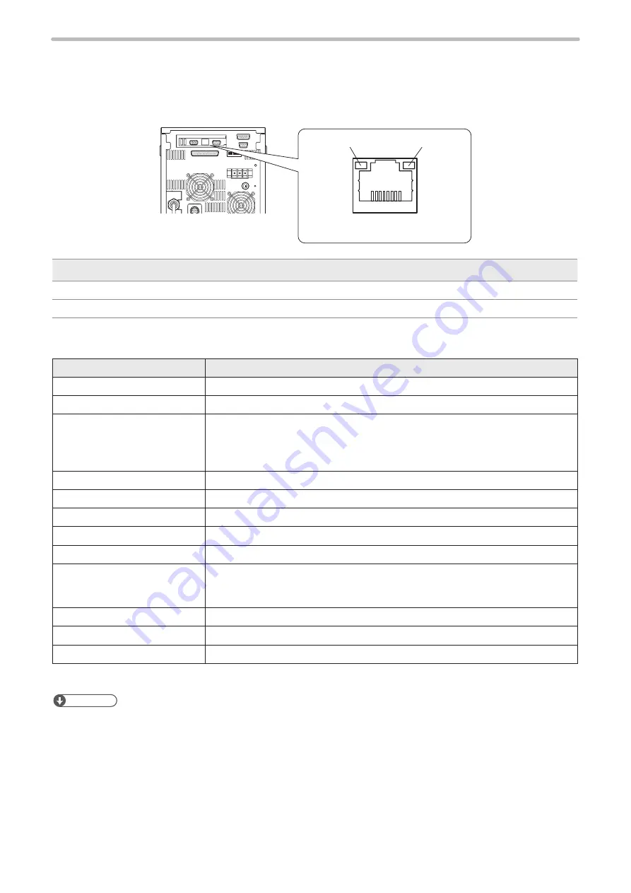
Rear of controller
RJ-45 8-pole connector
Orange LED
Green LED
Light color
Description
Green
Lights up while 1000 BASE-T Management port is in link-up state.
Orange
Blinks while there is activity on this port.
Ethernet communication conditions
Item
Ethernet communication conditions
Communication protocol
TCP/IP
Standards
IEEE802.3ab (1000BASE-T) / IEEE802.3u (100BASE-TX) / IEEE802.3 (10BASE-T)
Applicable cable
Category 5e or higher
• To connect an external device and one laser marker: Cross cable
• To connect an external device and two or more laser markers through a HUB or a
router: Straight cable
Applicable HUB (or rooter)
1000BASE-T / 100BASE-TX / 10BASE-T compatible
IP address
1.0.0.0 to 223.255.255.255 *1 / Initial value : 192.168.1.5
Subnet mask
128.0.0.0 to 255.255.255.254 / Initial value : 255.255.255.0
Default gateway
1.0.0.0 to 223.255.255.255 *1 / Initial value : Unspecified (0.0.0.0)
Port
5001 to 65534, except 9090 and 9091 / Initial value: 9094
Start code
• Setting request, Reading request, Reading response: STX
• Normal response: ACK
• Abnormal response: NAK
Check sum
OFF
Delimiter
CR fixed
Reception timer
Timeout monitoring ON (10 sec.)
*1 : Do not use “127” in the first octet.
ンㄆㄇㄆㄓㄆㄏㄆ
• Although the cable length between the devices is specified as 100 m at maximum in the Ethernet standard, use of cable
length below 10 m is recommended to avoid communication failure caused by noise and device malfunction.
• The communication control of the laser marker through the Ethernet should be performed in a secure network
environment.
• Depending on the combination, there are cases where IP Address and Subnet Mask values cannot be set even if they
are within the setting range.
• Make sure that the IP address for the laser marker on the network is not overlapping the IP address for the PC.
• If Ethernet is not used for the external control, connect nothing to the Ethernet port.
• For the details of the setting method of communication conditions, refer to “3-2-2 Communication condition setting”
ME-LPM-SSM-10
Summary of Contents for LP-M Series
Page 16: ...16 MEMO ME LPM SSM 10...
Page 27: ...27 Chapter 1 Specification ME LPM SSM 10...
Page 37: ...37 Chapter 2 Preparation ME LPM SSM 10...
Page 69: ...Chapter 3 Connection for External Control ME LPM SSM 10...
Page 128: ...Chapter 4 Maintenance ME LPM SSM 10...
Page 148: ...Troubleshooting ME LPM SSM 10...
Page 169: ...Index ME LPM SSM 10...
Page 172: ...172 MEMO No 9000 0066 34V ME LPM SSM 10...
Page 173: ...No 9000 0066 34V...


