147
■
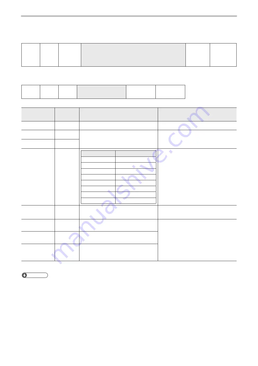
VEC logo conditions (CAD condition) : CDC
Sets the marking condition of VEC (work shape converted for laser marker) logo file.
Setting / Readout data of VEC logo
STX
CDC
Sub
command
[CAD No.] [X position] [Y position] [Scale] [Rotation angle]
[Laser pulse cycle correction] [Scan speed correction]
[Laser pulse cycle correction]
36-byte (LP-F10 mode), 33-byte (LP-F10W mode)
(Check sum)
Delimiter
Sub command is “S” at the time of setting and “A” for response data at the time of readout.
Readout request out of VEC logo
STX
CDC
R
[CAD No.]
2-byte
(Check sum)
Delimiter
Name
Data length
[byte]
Description
Remarks
CAD No.
2
“00”–“15”
X position
7
“-300.00”–“+300.00” [mm]
Specifies the origin coordinate of the logo.
Y position
7
Magnification
5
Model type*
Setting range [times]
LP-Sxx0
“00.10”–“01.98”
LP-Sxx5
“00.10”–“03.53”
LP-Sxx2
“00.10”–“01.21”
LP-Sxx0W
“00.10”–“02.27”
LP-Sxx5W
“00.10”–“04.04”
LP-Mxx0/LP-Zxx0
“00.10”–“03.03”
LP-Mxx5
“00.10”–“05.56”
LP-Mxx6/LP-Zxx6
“00.10”–“08.34”
Rotation angle
6
“-180.0”–“+180.0” [°]
The angle of rotation centering on the
origin position of CAD file, is indicated.
Laser power
correction
3
“000”–“200” [%]
•
The correction ratio is calculated using
the value set at the laser condition as
100%.
•
Laser Pulse Cycle Correction can be
specified only in LP-F10 mode.
Scan speed
correction
3
“050”–“200” [%]
(Laser
pulse cycle
correction)
(3)
“050”–“200” [%]
* For the detail of the model type, refer to “Target laser marker” (P.4).
Reference
• Logo file for the LP-F series is treated as one for LP-F10/F10W (marking area 90 mm x 90 mm). Logo file used for
special-order model (marking area other than 90 mm x 90 mm) is not supported.
• When a logo file for the LP-F series is used, X/Y scales are automatically adjusted to the same size in the LP-M/LP-S/
LP-Z series. X/Y scales for readout of CAD condition may be different from values specified in CAD condition setting.
• In readout response, the digit of 1 μm or 0.01° is rounded down.
•
The laser power correction, speed scan correction and laser pulse cycle correction are out of the setting range of the
LP-F10/F10W, readout cannot be performed. (NAK15 is returned.)
•
When the setting is performed using this command, the layer No. is “0”.
•
Setting with this command in the LP-F10W mode, the laser pulse cycle correction is set to 100%.
•
For LP-SxxxW type, the laser pulse cycle correction setting does not affect the marking. Also this setting is not saved in
the file.
ME-LPMSZ-SR-9
Summary of Contents for LP-M Series
Page 8: ...1 Before External Control ME LPMSZ SR 9...
Page 16: ...2 Basics of Serial Communication RS 232 Ethernet ME LPMSZ SR 9...
Page 34: ...3 Communication Command and Function ME LPMSZ SR 9...
Page 165: ...Troubleshooting ME LPMSZ SR 9...
Page 186: ...Character Code Table ME LPMSZ SR 9...
Page 199: ...Index ME LPMSZ SR 9...
Page 202: ...202 MEMO No 9000 0063 59V ME LPMSZ SR 9...
Page 203: ...No 9000 0063 59V...
Page 204: ...Panasonic Industrial Devices SUNX Co Ltd 2013 2019 March 2019 9000 0063 59V...


