


138
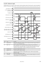
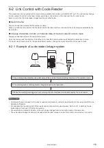
6-1-2 Operation flow
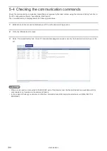
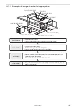
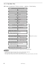
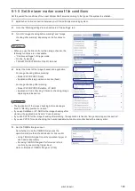
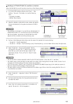
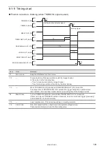
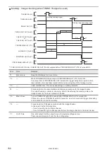
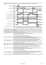
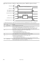
Example of operations for Position correction → Marking → Code checking
Laser marker: Laser radiation
• Reading and checkup of the marked code
• Output of checkup results
• Execution of shooting and checker
• Output of inspection results
Laser marker: Change of coordinates
Code reader: Operation start
Image checker: Operation start
Laser marker: Output of checkup results
Remote mode ON
Select File
Laser pumping ON
Shutter open
Start the image checker and laser marker
Start up and online connect the Laser Marker NAVI smart
Laser marker marking trigger input
Check the marking ready output ON
TIMING IN signal input *
TIMING IN signal input *
Repeat this procedure
* If it is set to use the TIMING IN signal, enter TIMING IN as a next operation trigger.
ンㄆㄇㄆㄓㄆㄏㄆ
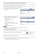
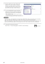
• Confirm the laser marker and image checker communication settings in advance.
• Set the conditions of files to use the image checker linkage function.
• The image checker linkage function can be used while the laser marker is under the remote control mode.
ME-LPRF-SM-11
Summary of Contents for LP-RF Series
Page 17: ...1 Product Overview ME LPRF SM 11...
Page 34: ...2 Laser Marker Installation ME LPRF SM 11...
Page 57: ...3 Operation Method ME LPRF SM 11...
Page 81: ...4 External Control Using I O ME LPRF SM 11...
Page 126: ...5 External Control by Communication Commands ME LPRF SM 11...
Page 135: ...6 Link Control with External Devices ME LPRF SM 11...
Page 160: ...7 Maintenance ME LPRF SM 11...
Page 186: ...Troubleshooting ME LPRF SM 11...
Page 214: ...Index ME LPRF SM 11...
Page 216: ...216 USB 32 55 W Warning 205 ME LPRF SM 11...
Page 217: ......


