


141
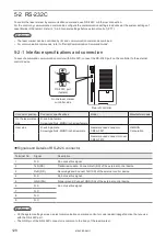
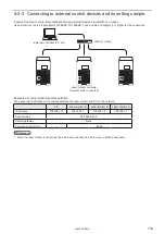
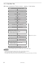
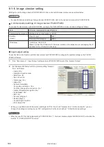
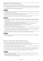
6-1-5 Set the laser marker overall file conditions
Set the overall file conditions of the Laser Marker NAVI smart according to the type of the system to establish.
1.
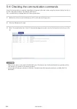
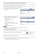
Establish an online connection between your PC and the laser marking system.
2.
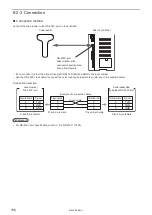
Go to the “Marking settings” screen and select “File settings” tab.
3.
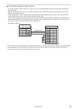
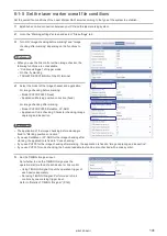
Turn ON “Image checking before marking” and “Image
checking after marking” depending on the functions to
use.
ンㄆㄇㄆㄓㄆㄏㄆ
• When you use the link control with an image checker, the
following functions are not available.
• “Continuous trigger” of trigger mode
• On-the-fly marking
• TARGET DETECTION IN of the I/O terminal
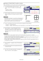
4.
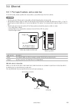
Select the model of the image checker and application.
For image checking before marking:
• Model: PV230/PV200 (fixed)
• Application: Marking position correction (fixed)
For image checking after marking:
• Model: PV230/PV200, DataMan, LP-ABR
• Application: Code checking, Character checking, Image
capturing and inspection
ンㄆㄇㄆㄓㄆㄏㄆ
• The application of the image checking before marking is
fixed to “Marking position correction”.
• If you use DataMan or LP-ABR for the image checking after
marking, the application is fixed to “Code checking”.
• If you use PV200 for the image checking after marking, the application is fixed to “Image capturing and inspection”.
• If you use PV230 for code checking, the human readable text can be also checked with a code symbol.
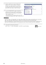
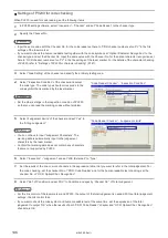
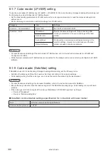
5.
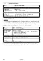
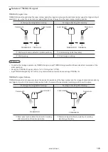
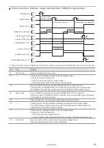
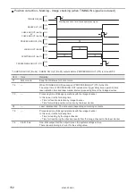
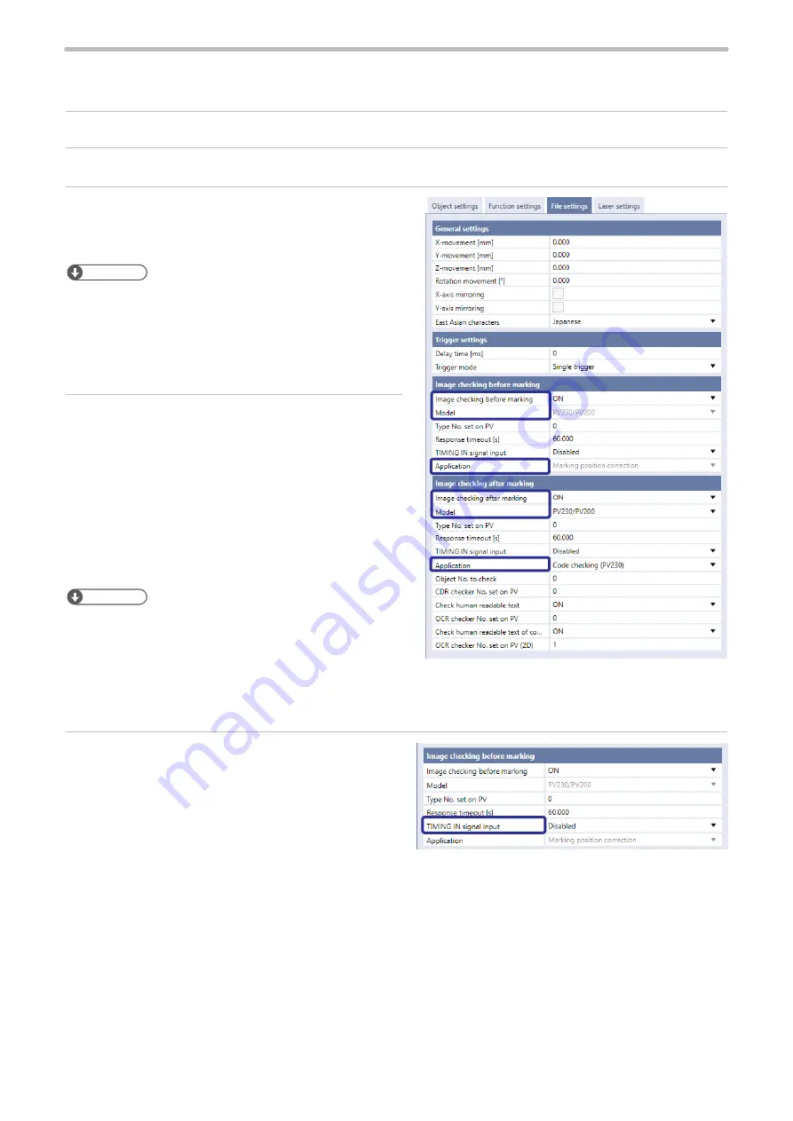
Set the TIMING IN signal input.
Set whether to use the TIMING IN signal as the
operation start method of each device for link control.
• Using TIMING IN signal: Input the operation trigger of
each device separately.
• Not using TIMING IN signal: Perform a set of link
controls by one marking trigger input.
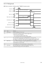
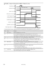
Refer to “Details of TIMING IN signal” (P.143).
ME-LPRF-SM-11
Summary of Contents for LP-RF Series
Page 17: ...1 Product Overview ME LPRF SM 11...
Page 34: ...2 Laser Marker Installation ME LPRF SM 11...
Page 57: ...3 Operation Method ME LPRF SM 11...
Page 81: ...4 External Control Using I O ME LPRF SM 11...
Page 126: ...5 External Control by Communication Commands ME LPRF SM 11...
Page 135: ...6 Link Control with External Devices ME LPRF SM 11...
Page 160: ...7 Maintenance ME LPRF SM 11...
Page 186: ...Troubleshooting ME LPRF SM 11...
Page 214: ...Index ME LPRF SM 11...
Page 216: ...216 USB 32 55 W Warning 205 ME LPRF SM 11...
Page 217: ......


