


36
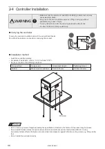
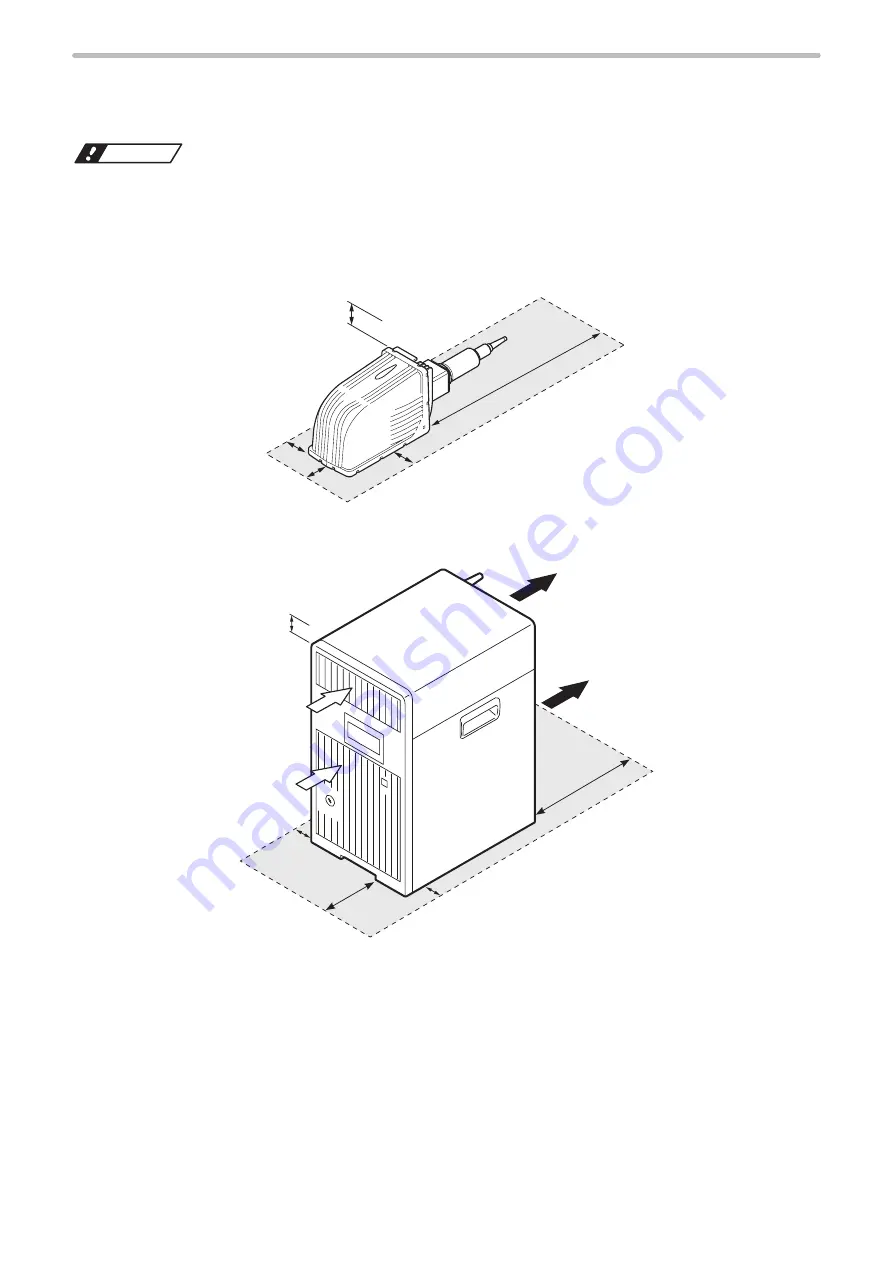
2-2 Installation Space
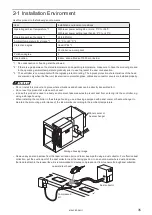
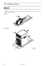
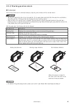
To keep the appropriate air cooling performance, provide space around the laser marker as shown in the following figure.
ワㄐㄕㄊㄆ
• To maintain the air-cooling performance of the laser marker, install both the head and controller in a well-ventilated
place.
• Installing near a heating element could cause the ambient temperature exceeding the specification range, which may
cause malfunction of the product.
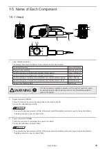
Head
470mm
50mm
50mm
50mm
50mm
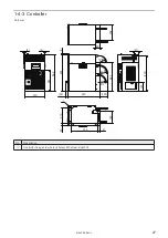
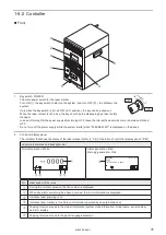
Controller
50mm
150mm
300mm
50mm
q
q
w
w
50mm
q
Intake
w
Exhaust
ME-LPRF-SM-11
Summary of Contents for LP-RF Series
Page 17: ...1 Product Overview ME LPRF SM 11...
Page 34: ...2 Laser Marker Installation ME LPRF SM 11...
Page 57: ...3 Operation Method ME LPRF SM 11...
Page 81: ...4 External Control Using I O ME LPRF SM 11...
Page 126: ...5 External Control by Communication Commands ME LPRF SM 11...
Page 135: ...6 Link Control with External Devices ME LPRF SM 11...
Page 160: ...7 Maintenance ME LPRF SM 11...
Page 186: ...Troubleshooting ME LPRF SM 11...
Page 214: ...Index ME LPRF SM 11...
Page 216: ...216 USB 32 55 W Warning 205 ME LPRF SM 11...
Page 217: ......


