


56
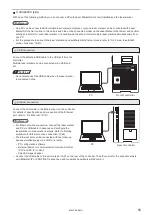
2-6 Construction of System
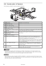
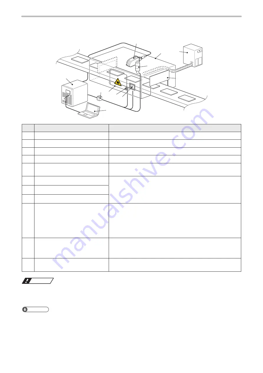
The following figure shows the construction sample of the system.
ABCD
ABCD
ABCD
BCD
a
u
w
y
q
i
o
t
r
e
1!
No.
Description
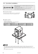
Installation and control sample
q
Laser marker head
-
w
Laser marker controller
-
e
PC for laser marker setting/monitoring
-
r
Protective enclosure
-
t
Laser protection shutter for work piece
gateway
Construct a control system which will separate (cut off) the laser beams
or shut off the laser power when it is opened.
y
Emergency stop button
Construct a control system for shutting off the laser power source when
it is opened.
u
Safety switch
i
Door for the maintenance
o
Safety relay unit or safety PLC, etc.
Connect both INTERLOCK 1 (X16, X17) and INTERLOCK 2 (X18,
X19) of the laser marker to the devices
t
to
i
using the relay output
terminal of the safety relay unit or the safety PLC.
Besides INTERLOCK terminals, it can also be connected to other I/O signals
such as LASER STOP terminals with the devices
t
to
i
depending on
the control specifications.
1)
Laser radiation warning light
To indicate the laser marker status, connect the output signals such
as ALARM OUT (Y15), LASER SUPPLY OUT (Y20) or LASING OUT
(No.40) to the light.
1!
Dust exhauster
Place the intake vent of the exhauster as close as possible to the
marking position of the work pieces.
ワㄐㄕㄊㄆ
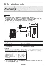
• INTERLOCK terminals (X16, X17 and X18, X19) are connected to the operating coil of the internal contactor in the
controller. Connect INTERLOCK (+) and INTERLOCK (-) in the I/O terminal with the non-voltage contact (dry contact)
such as a relay or a switch. Do not connect with the voltage contact such as a transistor.
ンㄆㄇㄆㄓㄆㄏㄆ
• When constructing a system compatible to ISO11553-1/ISO13849-1, construct the redundant interlock system by using
both INTERLOCK 1 (X16, X17) and INTERLOCK 2 (X18, X19) connected to safety PLC or safety relay unit to shut off the
laser power supply in accordance with the standards.
ME-LPRF-SM-11
Summary of Contents for LP-RF Series
Page 17: ...1 Product Overview ME LPRF SM 11...
Page 34: ...2 Laser Marker Installation ME LPRF SM 11...
Page 57: ...3 Operation Method ME LPRF SM 11...
Page 81: ...4 External Control Using I O ME LPRF SM 11...
Page 126: ...5 External Control by Communication Commands ME LPRF SM 11...
Page 135: ...6 Link Control with External Devices ME LPRF SM 11...
Page 160: ...7 Maintenance ME LPRF SM 11...
Page 186: ...Troubleshooting ME LPRF SM 11...
Page 214: ...Index ME LPRF SM 11...
Page 216: ...216 USB 32 55 W Warning 205 ME LPRF SM 11...
Page 217: ......


