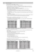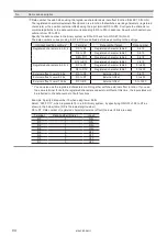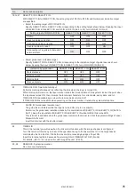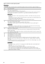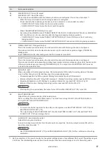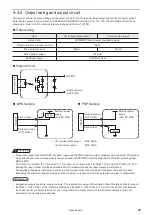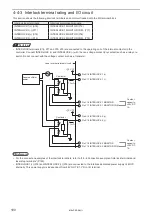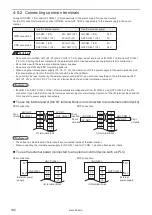
103
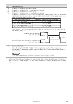
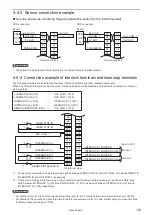
4-5-3 Sensor connection example
Use the sensor as a marking trigger (operate the sensor by the internal power)
24V OUT
IN COM. 1
0V OUT
0V OUT
OUT COM. 1
TRIGGER IN
VDD
OUT
0V
24V OUT
IN COM. 1
0V OUT
24V OUT
OUT COM. 1
TRIGGER IN
VDD
OUT
0V
X1
X2
X3
X4
X5
X6
X7
X8
Y1
Y2
Y3
Y4
Y5
Y6
Y7
Y8
X1
X2
X3
X4
X5
X6
X7
X8
Y1
Y2
Y3
Y4
Y5
Y6
Y7
Y8
I/O terminal block
I/O terminal block
NPN connection
Sensor
PNP connection
Sensor
ンㄆㄇㄆㄓㄆㄏㄆ
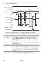
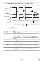
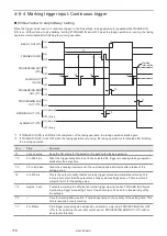
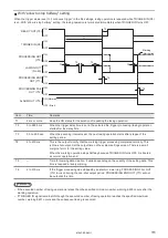
• The dotted line indicates that the terminals are connected inside of the laser marker.
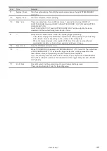
4-5-4 Connection example of interlock terminals and laser stop terminals
The following terminals are used to stop the laser radiation or disable the laser radiation temporarily.
When any of these terminals are disconnected, the laser radiation will be disabled and laser marker becomes in alarm or
warning status.
LASER STOP IN (X10)
―
OUT COM. 1 (X12)
LASER STOP IN (X11)
―
OUT COM. 1 (X12)
INTERLOCK 1(+) (X16)
―
INTERLOCK 1(-) (X17)
INTERLOCK 2(+) (X18)
―
INTERLOCK 2(-) (X19)
REMOTE INTERLOCK (X20)
―
OUT COM. 1 (X12)
INTERLOCK 1 MONITOR
INTERLOCK 1 MONITOR COM.
INTERLOCK 2 MONITOR
INTERLOCK 2 MONITOR COM.
INTERLOCK 1(-)
INTERLOCK 1(+)
INTERLOCK 2(-)
REMOTE INTERLOCK IN
INTERLOCK 2(+)
LASER STOP IN
LASER STOP IN
OUT COM. 1
N.O.
*2
N.O.
*2
*1
*1
*1
X7
X8
X9
X10
X11
X12
X13
X14
X15
X16
X17
X18
X19
X20
Y7
Y8
Y9
Y10
Y11
Y12
Y13
Y14
Y15
Y16
Y17
Y18
Y19
Y20
I/O terminal block
Monitor 2
Monitor 1
Input to PLC
*1 : Connect stop terminals such as a laser stop switch between LASER STOP IN and OUT COM. 1 as well as REMOTE
INTERLOCK IN and OUT COM. 1 respectively.
*2 : Connect non-voltage contact such as a relay output terminal including a safety device door, switches, safety relay
units between INTERLOCK 1(+) (X16) and INTERLOCK 1(-) (X17) as well as between INTERLOCK 2(+) (X16) and
INTERLOCK 2(-) (X19) respectively.
ンㄆㄇㄆㄓㄆㄏㄆ
• For details on the I/O circuit of the interlock terminals, refer to “4-4-3 Interlock terminal rating and I/O circuit” (P.100).
• For details on the operation of input terminals for safety measurement, refer to “Laser marker operation when functions
for safety measures are input” (P.90).
ME-LPRF-SM-11
Summary of Contents for LP-RF Series
Page 17: ...1 Product Overview ME LPRF SM 11...
Page 34: ...2 Laser Marker Installation ME LPRF SM 11...
Page 57: ...3 Operation Method ME LPRF SM 11...
Page 81: ...4 External Control Using I O ME LPRF SM 11...
Page 126: ...5 External Control by Communication Commands ME LPRF SM 11...
Page 135: ...6 Link Control with External Devices ME LPRF SM 11...
Page 160: ...7 Maintenance ME LPRF SM 11...
Page 186: ...Troubleshooting ME LPRF SM 11...
Page 214: ...Index ME LPRF SM 11...
Page 216: ...216 USB 32 55 W Warning 205 ME LPRF SM 11...
Page 217: ......

