62
No.
Description
t
Language
selection
Touch the language to select. The error information is displayed in the selected language.
• English
• Japanese
• Simplified Chinese
y
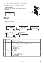
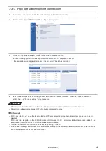
Indicates laser pumping is on. (including the incomplete period)
u
Indicates laser marker is in remote control mode (operated by an external device).
i
Tapping this icon moves to the model information display.
o
Tapping this icon returns to the previous display.
1)
Tapping this icon moves to the next display.
1!
Tapping this icon moves to the panel language selection.
*1 : The system clock can be adjusted in system settings screen of Laser Marker NAVI smart.
*2 : When the optional network unit is installed to the controller, the type of the network (EtherNet/IP or PROFINET), IP
address, and the version are displayed. If the network unit is not installed, the optional network is indicated as “None”
or “-----”.
Settings of controller display panel
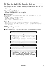
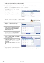
The backlight color and language of the display panel can be changed by Laser Marker NAVI smart.
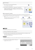
1.
Establish an online connection between your PC and the laser marking system.
2.
Go to the “System settings” screen.
3.
Select “Operation/information” tab.
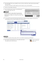
4.
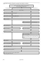
Configure the settings under “Controller display” if needed. Select the display panel color from white, pink or red at
following status respectively.
• Normal status (Initial setting: white)
• Warning status (Initial setting: pink)
• Alarm status (Initial setting: red)
ンㄆㄇㄆㄓㄆㄏㄆ
• When an alarm of error No. E000 to E199 occurs, the
display color always becomes red regardless of this setting.
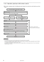
5.
Select the display language of the controller panel.
• English
• Japanese
• Simplified Chinese
ンㄆㄇㄆㄓㄆㄏㄆ
• The display language can be changed also with the controller panel directly.
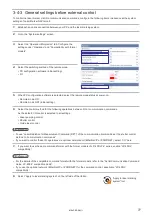
6.
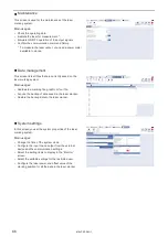
Select “Apply to laser marking system” on the left side of the ribbon.
The configured items will be applied to the laser marker.
“Apply to laser marking
system” tool
ME-LPRF-SM-11
Summary of Contents for LP-RF Series
Page 17: ...1 Product Overview ME LPRF SM 11...
Page 34: ...2 Laser Marker Installation ME LPRF SM 11...
Page 57: ...3 Operation Method ME LPRF SM 11...
Page 81: ...4 External Control Using I O ME LPRF SM 11...
Page 126: ...5 External Control by Communication Commands ME LPRF SM 11...
Page 135: ...6 Link Control with External Devices ME LPRF SM 11...
Page 160: ...7 Maintenance ME LPRF SM 11...
Page 186: ...Troubleshooting ME LPRF SM 11...
Page 214: ...Index ME LPRF SM 11...
Page 216: ...216 USB 32 55 W Warning 205 ME LPRF SM 11...
Page 217: ......

