105
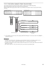
3-4-4 Connection example of laser stop terminals
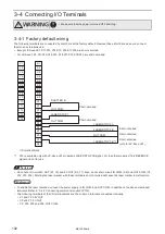
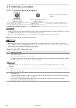
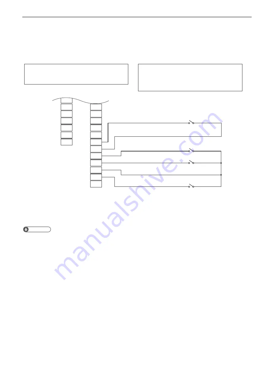
The following terminals are used to stop the laser radiation or disable the laser radiation temporarily.
When these terminals are disconnected, the laser radiation will be disabled.
Between LASER STOP terminals and OUT COM., an external device, such as door switch or laser stop switch can be
connected.
Except LP-Sxxx-LS1:
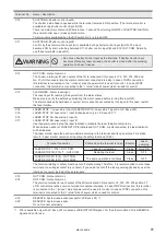
LASER STOP 1 (X14)
―
OUT COM. (X15)
LASER STOP 2A (X16)
―
OUT COM. (X18)
LASER STOP 2B (X17)
―
OUT COM. (X18)
For LP-Sxxx-LS1:
LASER STOP 1A (X14)
―
OUT COM. (X15)
LASER STOP 1B (X19)
―
OUT COM. (X18)
LASER STOP 2A (X16)
―
OUT COM. (X18)
LASER STOP 2B (X17)
―
OUT COM. (X18)
OUT COM.
LASER STOP 1
LASER STOP 2B
LASER STOP 2A
OUT COM.
LASER STOP 1B *1
Y8
Y9
Y10
Y11
Y12
Y13
Y14
X8
X9
X10
X11
X12
X13
X14
X15
X16
X17
X18
X19
X20
I/O terminal block
Laser stop switch, etc.
Laser stop switch, etc.
Laser stop switch,
door, etc.
(only for LP-Sxxx-LS1)
Laser stop switch, door, etc.
*1 : X19 is available only with LP-Sxxx-LS1 models as LASER STOP 1B signal. For the other models, X19 is RESERVE
signal and not for use.
ンㄆㄇㄆㄓㄆㄏㄆ
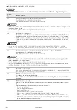
• To construct the interlock system to stop laser pumping and radiation forcibly by the hardware operation, use the
interlock connectors instead of LASER STOP terminals. Refer to “3-6 Interlock Connector” (P.118).
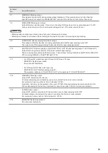
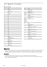
• For details on the operation of input terminals for safety measurement, refer to “Laser marker operation at inputting the
• OUT COM. terminals of Y2, X12, X15 and X18 are the common terminal connected internally.
ME-LPS-SSM-8
Summary of Contents for LP-S Series
Page 15: ...15 MEMO ME LPS SSM 8 ...
Page 26: ...26 Chapter 1 Specification ME LPS SSM 8 ...
Page 41: ...41 Chapter 2 Preparation ME LPS SSM 8 ...
Page 78: ...Chapter 3 Connection for External Control ME LPS SSM 8 ...
Page 126: ...Chapter 4 Maintenance ME LPS SSM 8 ...
Page 148: ...Troubleshooting ME LPS SSM 8 ...
Page 169: ...Index ME LPS SSM 8 ...
Page 172: ...172 MEMO No 9000 0066 16V ME LPS SSM 8 ...
Page 173: ...No 9000 0066 16V ...

